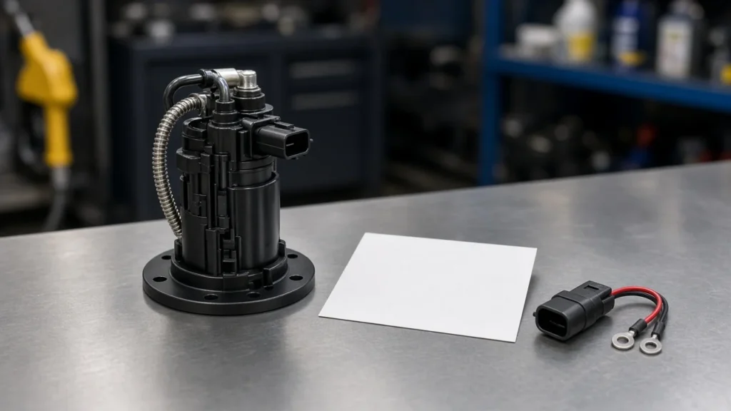
Fuel pump electrical connection work starts at the harness plug that feeds the pump—and often shares cavities with sender or signal pins—not at a color-memory guess. Before you source a module or kit, prove the connection under load with a voltage-drop decision, confirm pin roles, and reject melted or corroded terminals that will cook the next pump.
This page is a sourcing checklist: what the connection includes, what sits upstream, which drop thresholds matter, how pinout evidence beats wire colors, what visual failures look like, and when open-circuit battery voltage lies. Soft-link sister pages when the job turns into disconnect how-to, diagram reading, low-voltage causes, or full 12-volt wiring.

What a Fuel Pump Electrical Connection Actually Includes
It is the harness-to-module plug interface that carries pump power and ground, and often fuel-level or sensor pins on the same shell.
On in-tank modules, that plug is usually on the tank flange or nearby harness. Mechanically it looks like one connector. Electrically it can mix a high-current pump feed with thinner sender or reference circuits.
Procurement language often says “connector” when the real decision is pin roles plus terminal condition. A clean shell with the wrong cavity mapped still strands a truck. A correctly mapped shell with burned pins still kills a new motor.
Treat the fuel pump connector as evidence you collect before a quote—not as a decorative accessory that arrives with the pump carton.
Trace Power Upstream Before You Blame the Plug
Fuse, relay contacts, splices, and grounds can fail before the module plug ever opens.
Electric pumps draw meaningful current—trade bulletins often cite about 5–8 A or more depending on flow and pressure—so every upstream joint is a candidate for heat and voltage loss. A relay that clicks can still deliver a soft feed through burned contacts. A fuse that “looks fine” can still drop voltage in a fatigued holder.
Walk the path only far enough to decide ownership:
- Fuse and holder integrity → soft-link fuel pump fuses
- Relay coil vs contact health → soft-link electric fuel pump relay
- Full custom 12-volt install logic → soft-link how to wire a 12 volt fuel pump
- Harness color folklore for GM platforms → soft-link GM fuel pump wire colors
If upstream power and ground are solid yet the connection still fails a loaded check, stay on this page. If the complaint is “no power at all,” open the fuse/relay sisters first.
Voltage-Drop Decision at the Fuel Pump Connection
Measure voltage lost on the power side and the ground side while the pump circuit is actually energized.
Open-circuit readings at an unplugged shell can look healthy and still collapse once current flows. Independent technical explainers and manufacturer education both stress a fuel pump voltage drop check with the circuit loaded—often only a two-second key-on prime window unless you command the relay or keep the engine running.
| Decision cue | Typical guidance | What it means for sourcing |
|---|---|---|
| Delphi published procedure | Under 0.2 V drop on power side and on ground side under load | Tight target when following that method with proper probes |
| Common trade install/diagnostic guidance | About 0.5 V or less each side; more is excessive resistance | Practical shop gate for harness, connectors, and grounds |
| Motorservice contact bulletin cues | High current (often 5–8 A+); running plug voltage often near 12.5–13.0 V; large gaps vs onboard (example under 11 V) warrant contact inspection | Contact resistance is expensive at pump current |
Use two scopes without mixing them into one fake universal number: Delphi’s published method aims under 0.2 V per side; many trade procedures flag more than about 0.5 V per side as a problem. A Motorservice-style onboard-to-plug gap that grows toward a full volt-plus class cue is another reason to inspect contacts before you condemn the pump.
Important: High pump current turns a “small” corroded terminal into a large voltage loss and a comeback that looks like another bad pump. (Source: Motorservice fuel-pump contact bulletin)
Tip: Do not jab bare meter tips into terminals. Damaged cavities raise resistance and can overheat the next connection. (Source: Delphi voltage-drop education)
Use proper back-probes per Delphi’s voltage-drop education.
On some late systems a control module intentionally lowers voltage or PWM-drives the pump for speed control. That commanded drop is not the same failure mode as a brine-corroded tank-top plug. Confirm architecture before you treat every low reading as a bad connection.

Pinout Evidence for Sourcing: Roles Beat Wire Colors
Identify pump feed cavities with the factory diagram or a live measurement—wire colors are not a universal positive code.
Shop education is blunt: the positive pump feed is the conductor that goes live near battery voltage when the circuit is commanded. Colors vary by maker, year, and market.
Community threads show the same trap on multi-pin shells—someone measures about 5 V on a sender or reference cavity and thinks the “fuel pump connector” is underpowered, when the thicker pump power and ground cavities sit one row over.
| Cavity role | What it does | Sourcing implication |
|---|---|---|
| Pump power | High-current feed to the motor | Must match pump-only or module power pins |
| Pump ground | High-current return | Ground-side drop fails here as often as power-side |
| Fuel level sender | Gauge signal (often variable resistance) | Wrong pin map moves the gauge, not the pump |
| Sender low-ref / 5 V reference / sensor | Low-current PCM-side circuits on many multi-pin plugs | Easy to confuse with pump power on a quick meter sweep |
Call the high-current feed the pump power cavity and keep the fuel level sender on its own signal path when you write the quote notes.
For diagram literacy and 3-wire vs 4-wire module maps, open the in-tank fuel pump wiring diagram sister. This page only needs enough pinout evidence to stop a wrong quote.

Connector Health Checklist Before You Quote a Pump
Reject a blind pump-only quote when the shell shows heat damage, weak retention, or corrosion.
Trade diagnostics repeatedly tie melted or blue-tinted plastic, black soot at terminal entries, and loose retention clips to resistance under load. Tank-top connectors also sit where road de-icing chemicals accumulate and wick into seals.
Checklist before the purchase order:
- Lock and CPA/retention still hold the halves tight
- No melted shoulders or soot around power cavities
- Seals present and not crumbled
- No green/white corrosion on pins or splices near the tank
- Pump-to-hanger pigtail (on pump-only jobs) not brittle or cooked
After cleaning serviceable terminals, a light film of dielectric grease on seals can help keep moisture out—only on connectors that still have sound retention.
If the harness half is damaged, plan a repair pigtail or module packaging that includes a serviceable connector family. Do not assume the new motor will survive the old burned nest. Safe disconnect technique lives on how to disconnect a fuel pump electrical connector.

Open-Circuit Voltage vs Loaded Connection Readings
Require loaded proof at the connection; an unplugged battery-voltage reading can hide collapse under current.
Open-circuit tests are useful to spot a dead feed or open ground. They are not enough to clear a connection for sourcing. Community and shop cases often show healthy ground-side drop with an ugly power-side drop once the pump is connected and running—exactly the pattern that kills a replacement motor after a “we saw 12 volts” note on the repair order.
Procurement gate:
- Confirm pin roles (power vs sender).
- Inspect connector health.
- Run loaded voltage-drop (or loaded voltage vs battery) on power and ground.
- Only then open a printed-fitment pump or kit path.
Cause inventories for chronic low voltage belong on what causes low voltage to a fuel pump. Keep this page on the connection decision.
When to Use Sister Wiring and Voltage Pages Instead
Stay here for connection verification; open sisters when the job changes.
| Job | Better page |
|---|---|
| Release lock tabs without damaging terminals | How to disconnect fuel pump electrical connector |
| Read module pin maps and sender low-ref | In tank fuel pump wiring diagram |
| Inventory causes of low voltage | What causes low voltage to fuel pump |
| Build a full 12-volt pump feed | How to wire a 12 volt fuel pump |
| Relay or fuse detail | Electric fuel pump relay · Fuel pump fuses |
| OEM manufacturing context | OEM fuel pump manufacturer |
A fuel pump wiring harness complaint that is really a long power run or missing relay belongs on the 12-volt and relay sisters—not as a second copy of those pages here.
Choose Electric Pump Kits After Connection Checks Pass
After the connection clears, open a printed-fitment electric pump or installation-kit path—not a universal SKU guess.
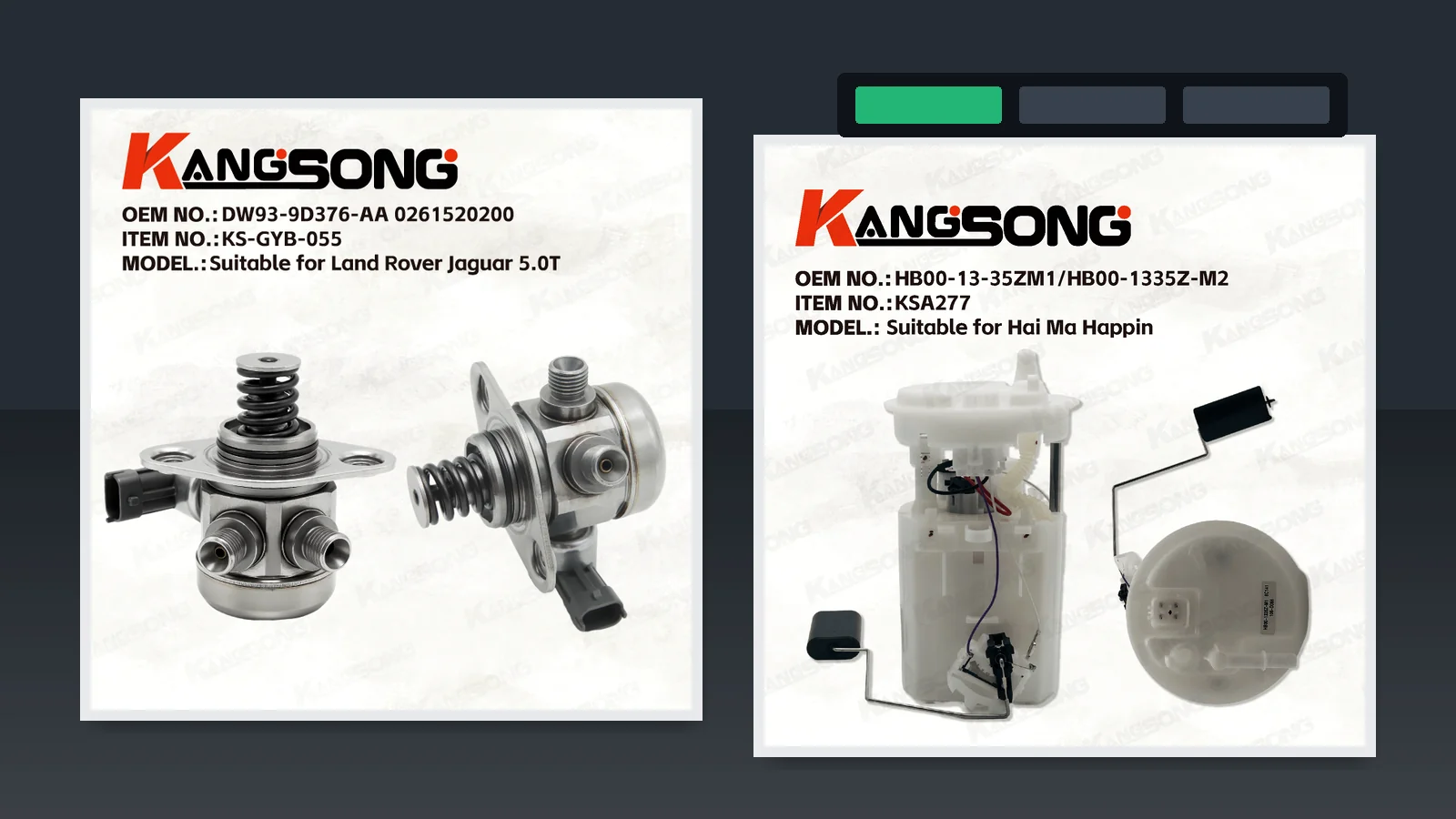
Kangsong lists electric gasoline fuel pumps with installation kits under printed vehicle and OE titles.
One example is the electric gasoline fuel pump with installation kit (printed 1987–1995 C/K coverage with printed OE references on that product page).
Related printed Accent/Sephia kit windows appear on the Hyundai/Kia-compatible electric pump listing. Browse the wider catalog from products root.
That electric fuel pump kit path is a printed-fitment installation kit example after connection checks pass—not a universal SKU.
Fitment stops at the printed title. Do not invent cross-brand equivalence, certificates, MOQ, or lead times from this article.
If the connection failed the loaded check, repair the harness or connector first. Shipping a kit into a burned plug only schedules the next return.

FAQ
What is a fuel pump electrical connection?
It is the harness/module plug interface that supplies pump power and ground and may also carry sender or sensor pins on the same shell.
How do I check a fuel pump electrical connection before ordering a pump?
Confirm pin roles, inspect the shell for heat or corrosion, then run a loaded voltage-drop check on power and ground during prime or commanded pump run.
What voltage drop is acceptable at the fuel pump connector?
Delphi’s published method targets under 0.2 V per side under load; many trade procedures treat more than about 0.5 V per side as excessive resistance. Use the method your shop follows and keep scopes separate.
Which wire is positive on a fuel pump?
The positive feed is the cavity that goes live near battery voltage when the pump circuit is commanded. Colors vary—use the factory diagram or a meter, not color memory.
Can a bad connection look like a bad fuel pump?
Yes. Low voltage from connection resistance can cut flow and pressure enough to mimic a failed motor on a gauge-only diagnosis.
Is 12 volts on an unplugged connector enough?
No. Open-circuit voltage can look fine and still collapse under load. Require a loaded check before you clear the connection.
Should the connector be replaced with the pump?
Replace or repair it when you see melt, soot, weak retention, or corrosion—especially on tank-top plugs exposed to road chemicals. A new pump in a burned nest is a planned comeback.
How is this different from an in-tank wiring diagram page?
The diagram sister teaches pin-role literacy on module maps. This page gates sourcing with voltage-drop decisions, pin evidence, and connector health checks.