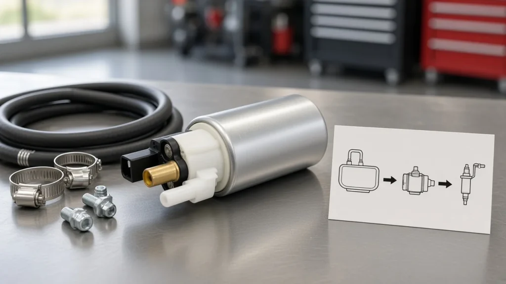
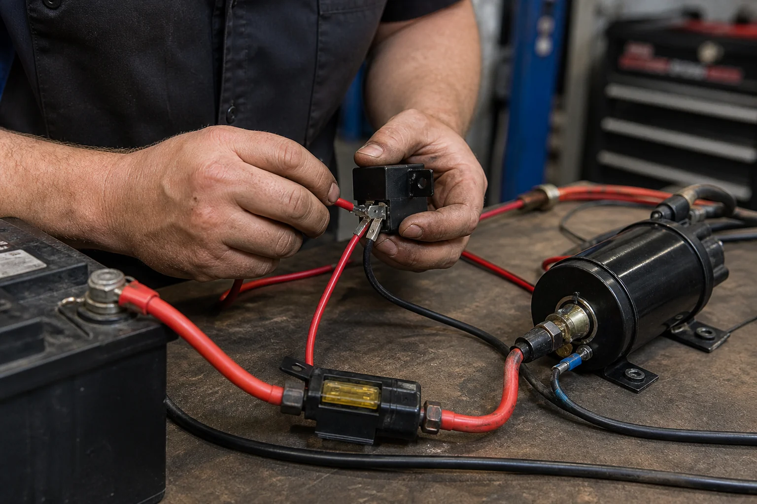
Confirm polarity, put pump current on a fused battery-to-relay feed, land a clean ground, then smoke-test—that is how to wire a 12 volt fuel pump without melting a harness or cooking a DC motor. This page covers polarity marks, the usual ISO relay pin map, fuse-near-battery placement, wire gauge, ground/voltage checks, and a short verification before fuel work. Spelling variants like how to wire a 12v fuel pump land on the same checklist.
Why a 12-Volt Fuel Pump Needs a Relayed, Fused Feed
Keep the pump’s high current on a fused battery→relay→pump path, and let ignition or ECU signals drive only the relay coil. A 12 volt electric fuel pump is a motor load. Running that current through an ignition switch, a thin factory trigger leg, or an unfused jumper to the battery is how switches overheat and underbody leads become firewood.
A relay is a remote heavy switch. A small current through the coil closes contacts that can carry the pump.
Mount the automotive relay so the fat battery feed stays short, then send only a light trigger to pin 86 (or the matching coil pin on your shell diagram). That pattern also cuts voltage drop: in a 12 V system, a little resistance on a long thin run shows up as a big loss at the pump.
Important: Do not wire the pump straight to the battery as an always-hot, unfused feed — source: maker install warnings + Hot Rod fuse-near-battery practice.
If someone asks you to “just hot-wire it to crank,” treat that as a temporary diagnostic only with a fused jumper and eyes on the wire temperature—not as the finished circuit. For continuous contact amp and ISO mini vs micro selection worksheets, hand off to what size relay for fuel pump rather than guessing from shopping titles here.
Confirm 12-Volt Fuel Pump Polarity Before You Energize
Find the positive terminal mark—or confirm flow direction on a controlled bench check—before the first key-on. Most automotive electric pumps are DC motors. Reverse polarity can damage the pump; some maker warranty notes treat reverse connection as excluded damage.
12 volt fuel pump polarity is not optional trivia: get pump polarity wrong and you may need a second pump before the vehicle ever leaves the bay.
Look for a stamped “+”, molded polarity marks, or unequal blade sizes called out in the pump sheet. When marks are missing, technicians often submerge the inlet in appropriate fluid, apply a fused 12 V supply briefly, and confirm the outlet moves fuel the correct way—then label the leads. Do that away from open fuel vapors and ignition sources.
12 volt fuel pump polarity mistakes show up as a dead pump, odd noise, or a unit that “ran once on the bench” and then failed after a rushed install. If you are reusing a vehicle harness plug, confirm the harness side still matches the new pump’s pin map before you force the connector home. Connector release technique itself belongs on how to disconnect fuel pump electrical connector—this page stops at polarity and feed planning.
ISO Relay Pin Map for an Electric Fuel Pump Circuit
On a typical ISO mini cube used as a normally-open fuel pump feed, pin 30 is fused battery in, pin 87 feeds pump positive, pin 85 is coil ground, and pin 86 is the low-current trigger. The fifth terminal (87a) on a SPDT cube is normally closed and usually stays unused and insulated for this job. Always match the printed diagram on the relay shell you actually bought—numbering is standard, but diode-suppressed coils care about coil polarity.
| Pin | Role in a typical NO pump circuit | Wire class |
|---|---|---|
| 30 | Fused battery (or other constant high-amp source) in | Heavy load (often 10–14 AWG) |
| 87 | Output to fuel pump positive | Heavy load (match pin 30) |
| 85 | Relay coil ground | Light trigger (often 16–18 AWG) |
| 86 | Relay coil trigger (ignition / ECU / oil-pressure path) | Light trigger |
| 87a | NC contact — usually unused for pump NO feed | Insulate if present |
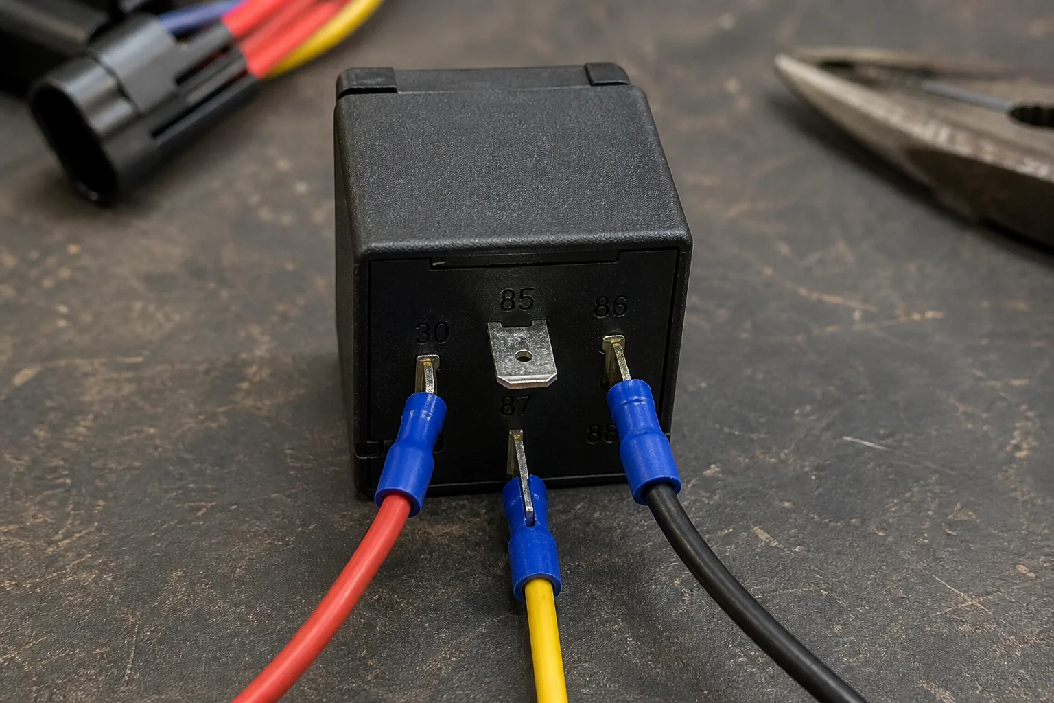
Common coil confusion: if one diagram grounds 85 and another grounds 86, both can be correct for a plain coil as long as the other pin gets the 12 V trigger. Diode-protected relays are different—follow the shell arrow or you can short the diode. Branded relay-kit shopping and kit-specific pre-checks live on Ron Francis wiring electric fuel pump relay kit; this page stays on the generic twelve-volt pattern.
Fuse Near the Battery and Wire Gauge for the Load Path
Place overcurrent protection on the battery feed to pin 30, as close to the power source as practical, and size the load wire for current and length. The inline fuse protects the wire. A short against the chassis halfway down the frame should blow the fuse before the insulation becomes a fuse.
A fuse near battery for fuel pump feeds is the rule that stops unprotected underbody cable from becoming the weak link.
Forum installs often stall on exactly this point: techs debate whether pin 30 goes to the battery or the starter solenoid BAT post, then forget the fuse. Either source can work when it can supply the pump amps—if it is fused or breaker-protected at the source. Maker sheets for performance electric pumps commonly pair a minimum 30 A class relay with a matching fuse example; treat that as a starting class, then confirm against your pump’s continuous draw and the sister sizing page when the load is edge-case.
| Circuit role | Common practice | Why it matters |
|---|---|---|
| Battery → fuse → relay pin 30 | Fuse near battery; heavy AWG | Protects the entire unprotected run |
| Relay pin 87 → pump + | Same gauge family as pin 30 feed | Limits voltage drop to the motor |
| Pump − → chassis / battery negative | Equal seriousness to the positive | Completes the DC loop |
| Trigger → pin 86 | Lighter AWG OK | Coil current is small |
| Absolute minimum load wire (many maker sheets) | 14 AWG or larger | Undersize wire heats and starves the pump |
| Long / high-current runs | Step up to 12 or 10 AWG | Length adds resistance |
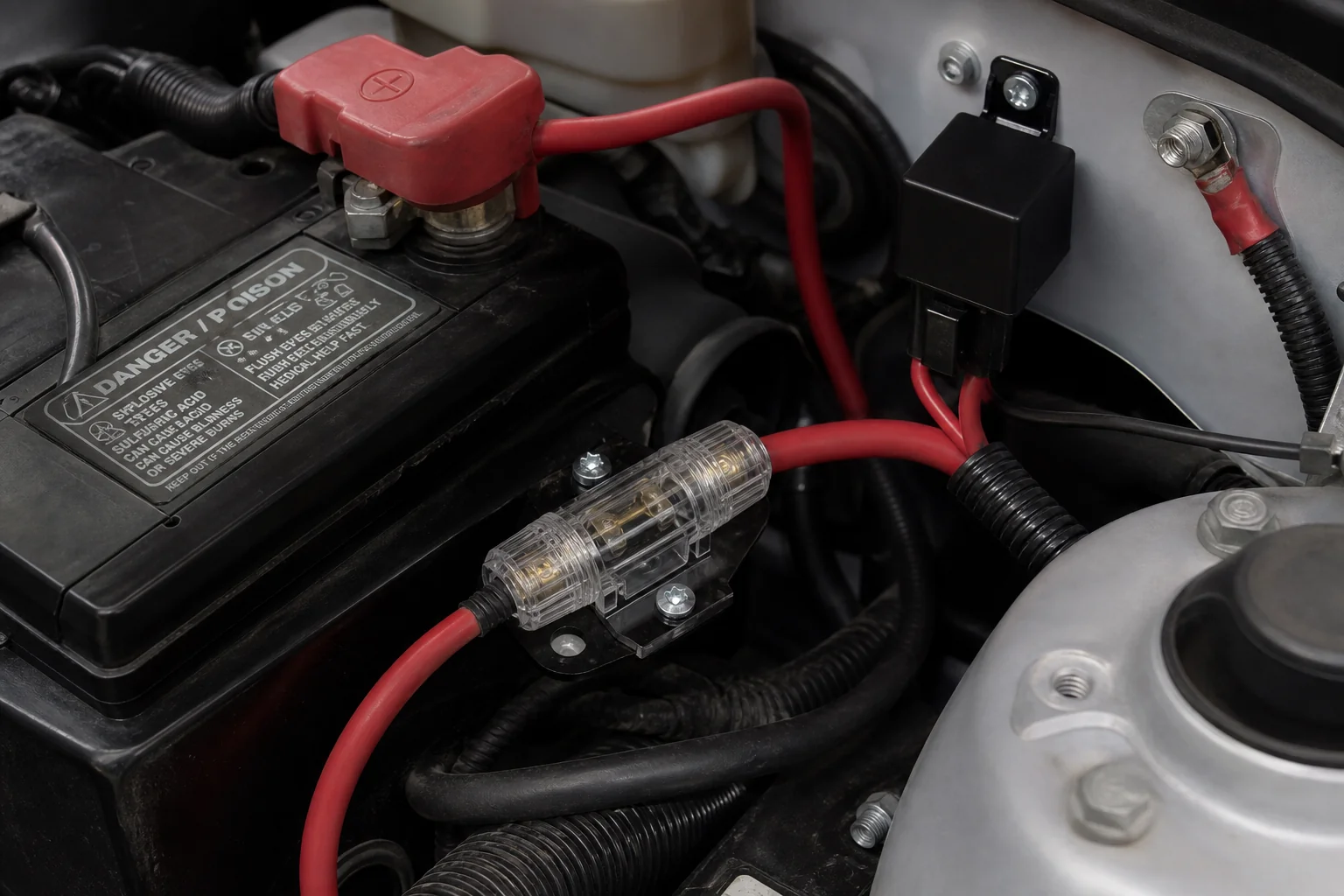
How to wire a 12v fuel pump on a long bed truck is mostly a wire-length problem: the same amp that is fine on a short hatchback run needs heavier cable when the pump sits at the rear. If you need a meter procedure for an existing fuse that already blew, use how to test a fuel pump fuse—this section is placement and gauge planning, not continuity lab work.
Ground Path and Voltage Drop at the Pump
Treat the chassis ground like the positive feed: clean metal, tight ring terminals, and enough wire gauge (AWG) that the pump still sees healthy voltage while running. Preferred practice on many install sheets is a ground path that references the battery negative, not a painted seat bolt that looks convenient.
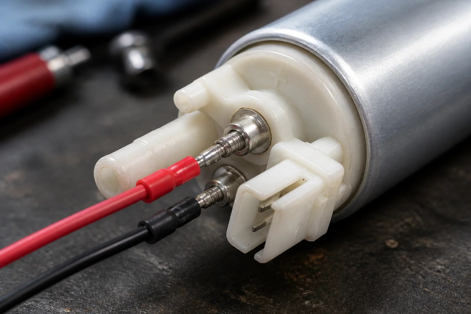
After the circuit is built, measure voltage at the pump with it running. Modern charging systems often sit around the low-to-mid 13 V range at the battery; install guidance for high-flow pumps frequently targets about 13.5 V at the pump under load. A large gap between battery voltage and pump voltage means you are paying resistance tax in the feed, the ground, a weak crimp, or a warm relay contact—not “a weak pump” by default.
Star washers that bite through paint, dielectric grease kept out of the clamp face, and loom that cannot rub the exhaust are boring details that prevent comebacks. Route clear of moving suspension and heat sources; secure the new run so vibration cannot frett the insulation through.
Optional Safety Switches on the Trigger Path
Put an oil-pressure safety switch or inertia failsafe on the low-current trigger path—they are not a substitute for the fused relayed load feed.
Street and hot-rod patterns often use a normally-open oil-pressure switch so the pump cannot stay powered after a stall or crash once oil pressure collapses. An inertia (impact) switch in series with the trigger adds another cutout.
Because oil pressure is zero while cranking, those layouts need a cranking bypass (starter “S” feed and/or a diode path) so the pump still primes during start.
Keep this section short on purpose. Deep kit-style oil-pressure / inertia wiring narratives and branded relay-kit shopping belong on the Ron Francis sister page.
If you add safety switches, wire them into the coil trigger, keep the fat fused feed intact, and verify cranking still primes the pump.
Smoke Test and Voltage Check Before Fuel Work
Power the circuit briefly, confirm the relay clicks, the pump primes the right way, voltage at the pump looks sane, and nothing smells hot—before you trust the wiring with a full fuel system. A practical smoke test is not theater; it is a short, controlled power-up with the battery connected, fuse installed, and eyes on the new harness.
- Re-check polarity marks and pin-30 fuse presence.
- Key-on or trigger the coil; listen for the relay click.
- Confirm the pump runs the expected direction / prime sound (fuel present and safe containment).
- Meter voltage at the pump under load; chase large drops.
- Feel the fuse holder, relay body, and long runs for abnormal heat after a short run.
- Kill power and inspect for melted loom or loose grounds before road use.
If the relay clicks but the pump is silent, you have a load-side or ground problem, not a “bad coil” by default. If the relay never clicks, chase the trigger and coil ground first. Mechanical tank-module seating, lock rings, and seal work remain on how to install fuel pump assembly.
Browse Kangsong Electric Fuel Pump Products with Installation Kits
After the wiring pre-check is planned, browse a scoped DC twelve-volt installation kit electric pump with harness provisions—not a random assembly photo and not a third-party relay-kit claim. Kangsong publishes electric fuel pumps and assemblies through the products catalog. One concrete example is the electric gasoline fuel pump with installation kit (WP product ID 2551): working voltage DC 12V, accessories included, main connector listed as 2Pins, with OE/year scope on 1987–1995 C/K 1500/2500/3500 pickups (E3902-class interchange framing on the product page).
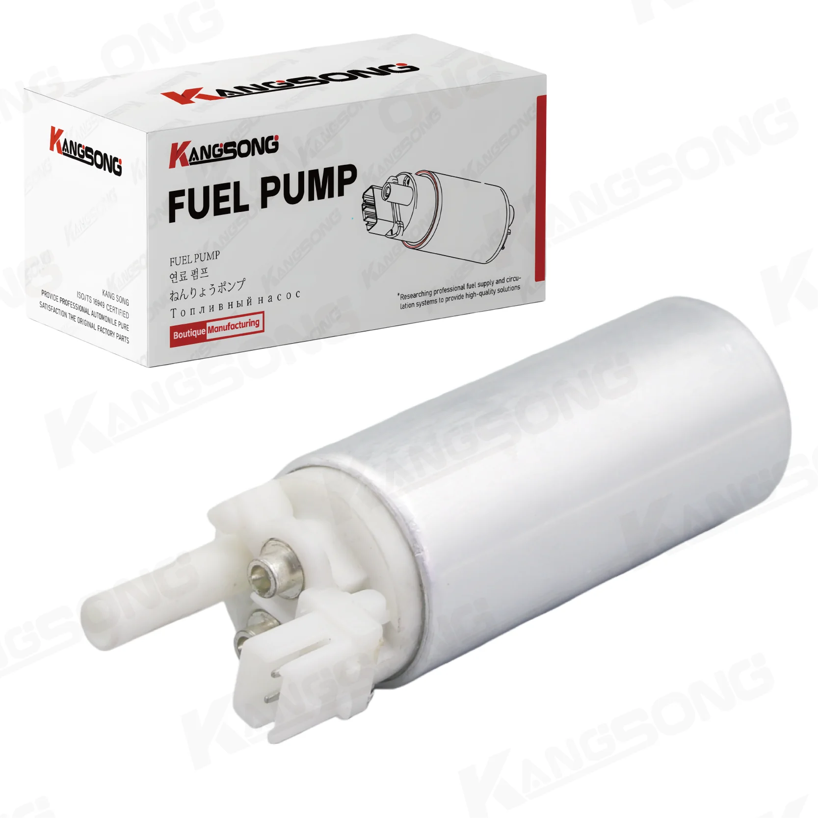
Confirm vehicle and OE fitment on that product page before ordering. Kangsong does not claim equivalence to branded relay wiring kits, and this recommendation is not a default Sonata/Optima assembly slot. When fitment falls outside 2551’s window, stay on the products-root category and match the listed application—do not invent universal fit from a wiring article.
FAQ
Can I wire a twelve-volt fuel pump straight to the battery?
Not as a finished, always-hot, unfused circuit. Use a fuse at the battery feed and a relay (or other controlled switching) so the pump is not permanently live and the wire is protected.
How do I know which wire is positive on a 12 volt fuel pump?
Use the stamped “+”, the maker pin chart, or a brief fused bench check that confirms correct flow direction—then label the leads before the vehicle install.
What happens if I reverse polarity?
Reverse polarity can damage a DC fuel pump motor. Confirm polarity before the first sustained power-up.
Do I need a relay to wire a 12 volt fuel pump?
For most electric pumps, yes. Keep high current on a fused battery feed through relay contacts; use ignition/ECU/oil-pressure circuits only as the coil trigger.
Where should the fuse go when I wire a twelve-volt fuel pump?
On the high-current feed to relay pin 30, as close to the battery (or other power source) as practical so the entire unprotected run is covered.
What wire gauge should I use for a twelve-volt fuel pump?
Many maker sheets call for 14 AWG or larger on the load path; long runs and higher current often need 12 or 10 AWG. Match ground gauge to the positive feed seriousness.
Does it matter whether relay pin 85 or 86 is grounded?
On a plain coil, either pin can be ground if the other is the 12 V trigger. Diode-suppressed relays need the polarity shown on the shell.
What is a smoke test after fuel pump wiring?
A short controlled power-up: relay click, correct pump prime, voltage check at the pump, and a heat/odor inspection before you rely on the circuit with fuel.
References
- Safe and efficient electric fuel pump wiring (HOT ROD Network) — relayed feed, fuse near battery, ISO pin roles, oil-pressure failsafe pattern.
- Automotive Relays 101 (Waytek Wire) — coil vs contacts, ISO mini/micro contact bands, diode coil notes.
- OSHA 29 CFR 1910.106 Flammable liquids — workplace flammable-liquid / ignition-source safety framing near fuel work.
- Correct in tank fuel pump polarity (Alfa Romeo Forums) — real-user DC polarity marks and rotation-direction concern.
- Can I wire fuel pump directly to battery? (r/MechanicAdvice) — community battery-direct objection language.