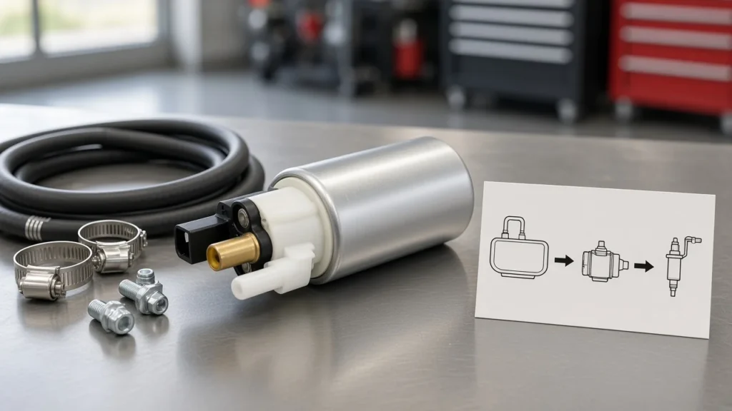
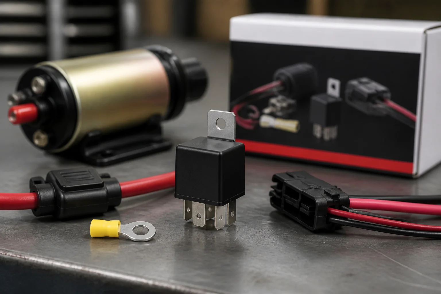
A ron francis wiring electric fuel pump relay kit pattern is a fused battery feed into relay pin 30, pump positive on 87, coil ground on 85, and a low-current ignition/ECU/oil-pressure trigger on 86—not an ignition-switch–powered pump feed. Treat market kit titles as SERP entry language for that same electric fuel pump relay wiring discipline. Walk the install pre-check, pin map, fuse and wire plan, failsafe triggers, and smoke-test before any fuel-line work.
Why Electric Fuel Pumps Need a Relay Kit Feed
Keep pump current on a fused battery→relay→pump path; let ignition, ECU, or oil-pressure circuits drive only the relay coil.
An electric fuel pump is a high-current load. A fuel pump relay is the electromechanical switch that keeps that load on a short battery feed while a low-current signal only energizes the coil. A relay kit (market exemplar Ron Francis FP-35/FP-36) is simply packaged hardware for that pattern—shopping the kit does not replace learning the pins.
Important: Treat fuel vapor and live electrical work as an ignition-risk environment—disconnect the battery before splicing, keep sparks away from open fuel, and fuse the high-current feed (OSHA 29 CFR 1910.106).
Counters and builders refuse ignition-switch–powered pumps for the same reason kit marketing does: dashboard switches and thin harness legs are not built to carry continuous pump amps. How to wire electric fuel pump relay circuits therefore starts with moving the load onto a fused battery path, not with searching for a thicker ignition wire.
Installation Pre-Check Before You Splice
Disconnect the battery, treat fuel vapor as ignition risk, confirm trigger type and ISO mini vs micro socket fit, then decide failsafe options before you cut any harness.
Run this checklist before the first splice so you are not inventing the circuit under a dripping fuel line.
| Pre-check item | Pass condition | If it fails |
|---|---|---|
| Battery / power isolation | Negative cable disconnected before cutting or crimping | Stop; isolate power first |
| Fuel vapor / spark hygiene | No open fuel, no grinding sparks near the tank or lines | Clear vapor sources; delay wiring |
| Socket form factor | ISO mini vs micro body matches the socket | Do not force a cube that will not seat |
| Trigger source named | Ignition, ECU ground-side, oil-pressure path, or mix written on the ticket | Decide before landing pin 86 |
| Load protection plan | Fuse or breaker location marked near the battery/power source | Do not run an unfused always-hot feed |
| Failsafe decision | Oil-pressure and/or inertia yes/no recorded, with cranking bypass if oil-pressure is used | Add parts before final loom tape |
Automotive plug-in cubes follow ISO 7588-style terminal allocation and dimensional families. Confirm the relay body matches the socket before assuming any “30 A / 40 A cube” will plug in—form-factor literacy is separate from contact amperage selection on the sibling sizing article.
ISO Pin Map: 30, 85, 86, 87, and 87a
On a typical normally-open fuel-pump circuit, 30 is fused battery in, 87 feeds pump positive, 85 is coil ground, and 86 is the low-current trigger; leave unused 87a insulated.
How to wire a relay for electric fuel pump work collapses to that ISO terminal 30/85/86/87/87a map on a common cube. Always read the printed diagram on the shell—numbering is standardized, but shells still differ.
| Pin | Function on a typical NO pump circuit | Wire class |
|---|---|---|
| 30 | Fused battery / constant power into the relay | Heavy load feed |
| 87 | Output to electric fuel pump positive | Heavy load feed |
| 85 | Coil ground (or polarity per diode-suppressed shells) | Light coil leg |
| 86 | Coil trigger from ignition, ECU, or oil-pressure path | Light trigger leg |
| 87a | Normally closed contact on 5-pin SPDT cubes | Usually unused—insulate |
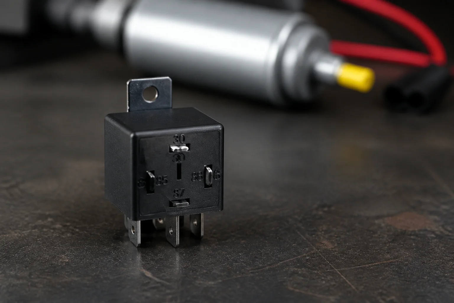
Four-pin NO cubes omit 87a. Five-pin SPDT cubes still work as NO pump switches when 87a is capped. Coil polarity matters on diode-suppressed relays; load pins 30 and 87 are not interchangeable with the coil pair.
Fuse, Wire Gauge, and Relay Mount Location
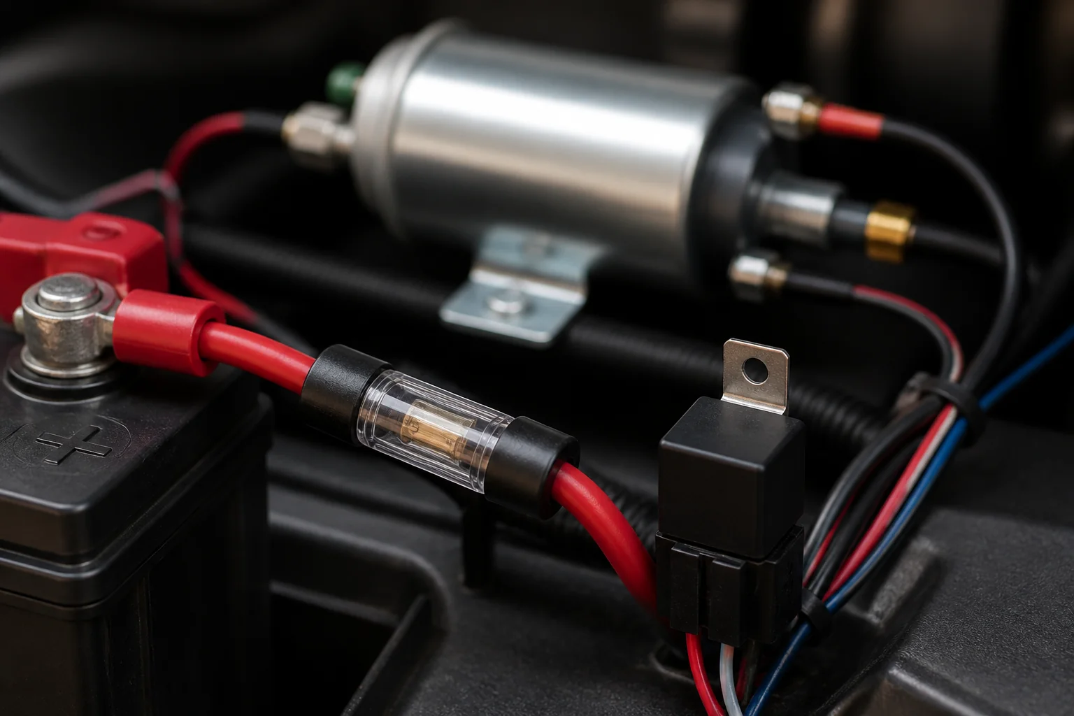
Place overcurrent protection on the battery feed to pin 30 as close to the power source as practical; use heavy conductors on the load path and lighter wire on the trigger path.
An inline fuse / circuit breaker protects the wire, not the marketing amp printed on a kit bag. Field guides commonly call for the fuse within about 12 in of the battery or other power takeoff. Exact fuse amp still follows wire gauge and pump draw—use what size relay for fuel pump for contact-class selection and how to test a fuel pump fuse for meter steps.
Wire gauge (load vs trigger) practice pairs roughly 10–14 AWG on battery→relay→pump feeds and lighter 16–18 AWG on coil legs. Mount the relay to keep the heavy run short—near the battery or pump end of the feed—so voltage drop stays low.
Tip: Fuse amp and relay contact amp are different decisions—size contacts on the sibling relay article, then protect the conductor with a fuse matched to the wire.
Contact amperage selection stays on that sizing page. The pre-check here only locks the placement: fused feed on 30, heavy load path, light trigger path.
Trigger Choices: Ignition, ECU, Oil-Pressure, and Inertia
Simple switched 12 V works for many installs; oil-pressure and optional inertia on the trigger stop a runaway pump after stall or crash—and need a cranking bypass so the pump still runs while starting.
Ignition / ECU trigger options land on pin 86 as a low-current control. Some harnesses use a factory pump feed cut and redirected to 86 while a new fused battery feed owns pin 30. ECU ground-side drivers still only see coil current when the relay is correctly suppressed and polarized.
An oil pressure safety switch on the trigger side can shut the pump off when oil pressure is lost after a stall or crash. An inertia / crash switch adds impact protection on the same control path. Both patterns need a cranking feed or diode bypass so the pump primes before oil pressure builds—shop threads often confuse the oil-pressure “S” terminal with relay pin 30.
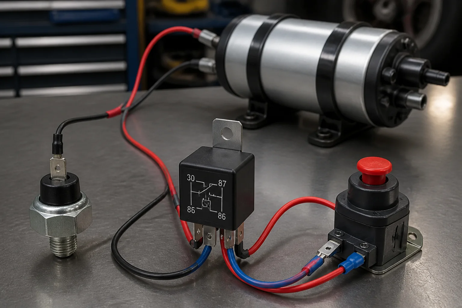
From the field: Ford truck builders frequently ask whether oil-pressure “S” lands on the starter solenoid “S” and whether relay “30” is a fused battery takeoff—keep failsafe switches on the coil/trigger side and keep fused battery power on pin 30 (Ford Truck Enthusiasts thread).
Smoke-Test the Relay Circuit Before Fuel Work
Confirm relay click and pump prime on the planned trigger before you open fuel lines; then branch to amp sizing, fuse testing, or broader electrical diagnosis on sibling articles if the circuit still fails.
With the battery reconnected and fuel lines still closed, key-on or command the planned trigger and listen for the relay click. A silent cube points at coil power, ground, or a form-factor mismatch. A click with no pump hum points at the load feed, fuse, pump ground, or the pump itself.
Only after click and prime look healthy should you leak-check fittings and move fuel. If the complaint is still electrical after a sound relay path, use fuel pump electrical problems. If the architecture question is external versus in-tank, use external fuel pump vs internal instead of expanding this wiring pre-check.
Choose a Kangsong Electric Pump with Installation Kit
After the relayed feed plan is set, browse Kangsong electric pumps and install kits inside each product’s listed application—without presenting them as Ron Francis relay-kit replacements.
Kangsong publishes the catalog at the products-root category. The Kangsong electric pump with installation kit (2551) example—Electric Gasoline Fuel Pump with Installation Kit—lists DC 12 V operation, accessories included, flow about 43.3–49.5 GPH, and a 1987–1995 C/K pickup OE window on the product page. Use that page only when years and OE refs match.
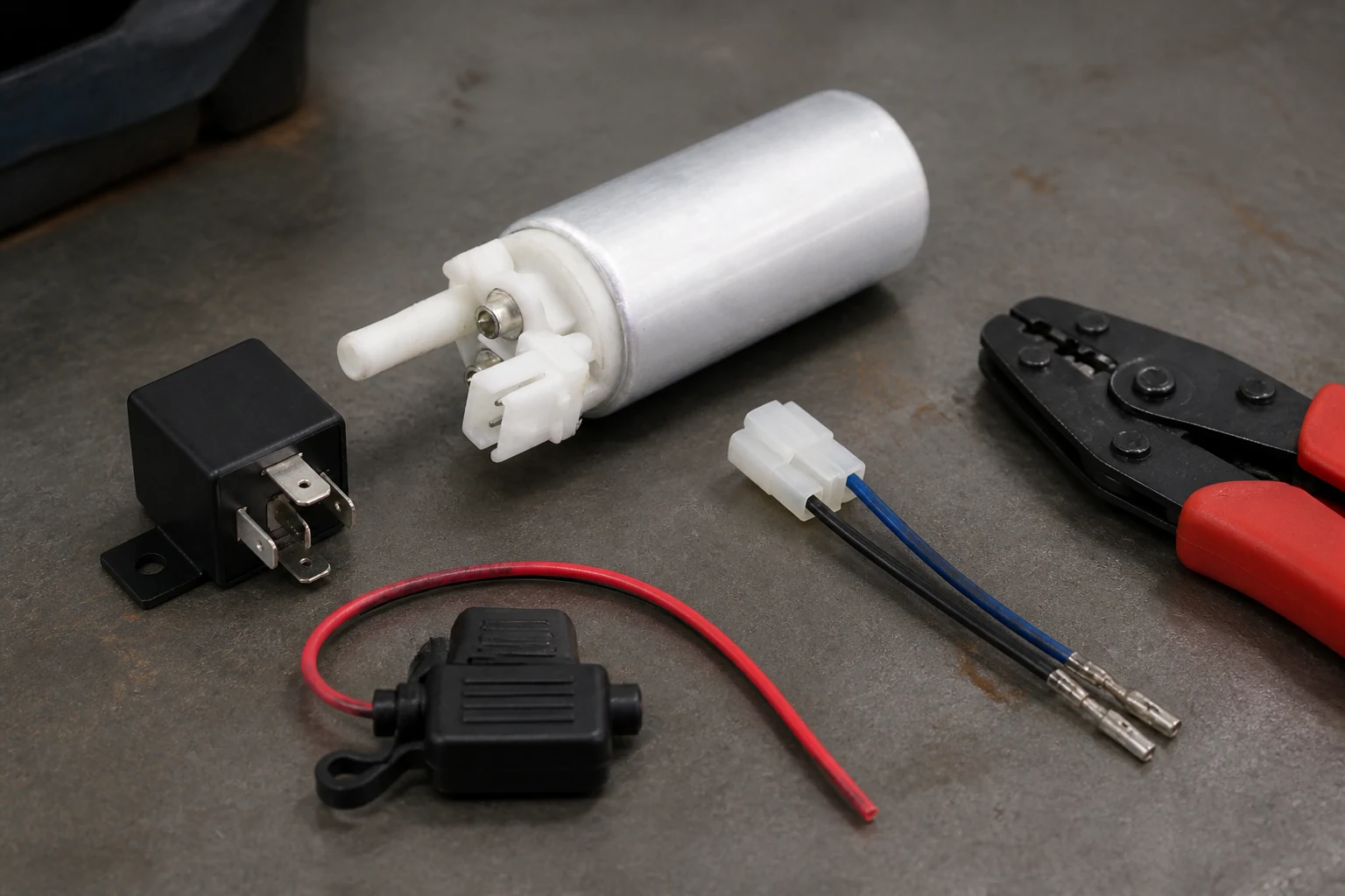
How to wire an electric fuel pump with a relay still ends at hardware that fits the vehicle. Kangsong does not sell Ron Francis Wiring relay kits and does not claim equivalence to FP-35, FP-36, or related SKUs. Skip the pump path when the unresolved job is still amp class, fuse continuity, or a wiring short.
FAQ
How do I wire an electric fuel pump relay?
Feed fused battery power to pin 30, take pump positive from 87, ground the coil on 85, and apply a low-current ignition/ECU/oil-pressure trigger on 86. Keep the high-current path short and fused near the battery.
Do I need a relay for an electric fuel pump?
Yes for most aftermarket electric pumps—the pump’s high current should not ride on an ignition switch or undersized harness leg. The relay keeps that load on a fused battery feed while the switch only drives the coil.
Can I wire my fuel pump straight to the battery?
Not as an unfused, always-hot feed. If you take power from the battery, fuse it near the source and switch it through a relay with a controlled trigger so the pump cannot run uncontrolled.
What pins are on a fuel pump relay (30/85/86/87)?
On a typical ISO cube used for a fuel pump, 30 is fused battery in, 87 feeds the pump, 85 is coil ground, and 86 is the trigger; 87a on five-pin shells is usually unused and insulated for NO pump circuits.
Where does the oil-pressure switch go in a relayed pump circuit?
On the trigger/coil side so loss of oil pressure drops pin 86 (or the control feed into it), not as a substitute for the fused battery feed on pin 30. Add a cranking bypass so the pump still runs while starting.
What size wire and fuse do I need on the load side?
Field practice often uses roughly 10–14 AWG on the load path and 16–18 AWG on the trigger, with the fuse near the battery sized to protect the wire. Exact amp class for the relay contacts belongs on the what size relay for fuel pump article.
Does Kangsong sell a Ron Francis relay kit / is it compatible?
No. Kangsong lists electric pumps and install kits at products-root; it does not equal, replace, or cross-reference Ron Francis Wiring relay kits. Browse pump hardware only inside each product’s stated OE/year window.
Can I replace a mechanical pump with an electric pump using only a relay?
A correctly wired relay is necessary for the electrical feed, but it is not sufficient for a full mechanical-to-electric conversion. You still need pump placement, plumbing, pressure strategy, and vehicle-specific controls beyond this wiring pre-check.
References
- ISO 7588-1:1998 preview — road-vehicle relay terminal allocation.
- Waytek Wire — Automotive Relays 101.
- OSHA 29 CFR 1910.106 — Flammable liquids.
- HOT ROD — Safe and efficient electric fuel pump wiring.
- GTSparkplugs — Electric fuel pump wiring.
- The H.A.M.B. — Electric Fuel pump relay thread.
- Ford Truck Enthusiasts — Electric fuel pump with oil pressure switch wiring.