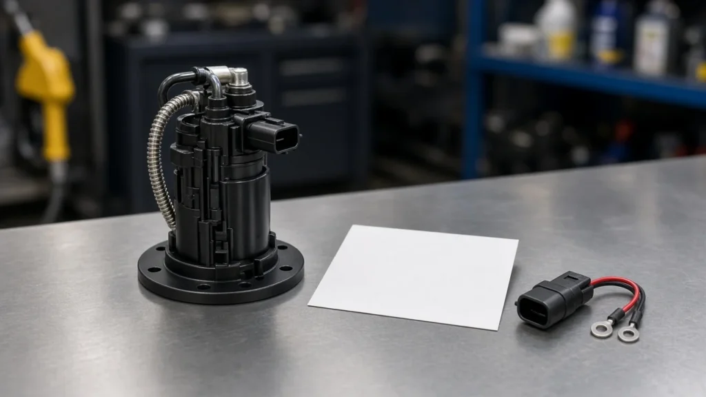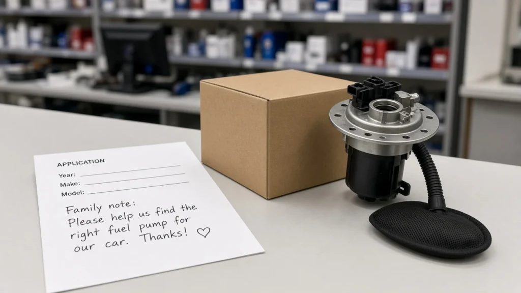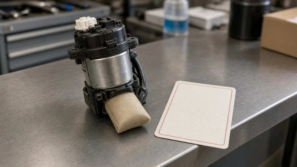

In tank fuel pump connector identification starts at the tank module flange—not at a frame-rail driver box and not at a color-memory guess. Count cavities, split thick pump leads from thin sender leads, and photograph both faces before any RFQ.
This page absorbs in tank fuel pump electrical connections on that same flange family: which interface you have, how pin roles split, when a numbered pigtail still needs a map, and which printed Kangsong in-tank path to open after the family matches.
Which In-Tank Connector Are You Actually Looking At
It is the tank-module/flange plug family, not the driver-module connector.
Shops and importers mix three nearby interfaces. The vehicle body harness plug snaps to the tank. A fuel pump flange connector sits on the locking-ring lid.
Short in-tank leads then run from that lid down to the pump motor and fuel level sender.
Call the whole set in tank fuel pump electrical connections. A frame-rail fuel pump driver module connector is a different family—soft-link that sister when the box is under the vehicle, not on the tank.
| Interface | Where you find it | What it proves |
|---|---|---|
| Body harness plug | Cabin, under-seat, or tank-access cover | Vehicle-side pin count and weather seals |
| Flange connector | Tank-top locking ring | Module family the lid presents to the harness |
| In-tank leads | Under the flange, pump to hanger | Continuity after the body plug already looks live |
A clean body plug with open flange-to-pump wires still leaves a silent pump. Photograph the lid and the harness face before anyone writes a line item.
Count Cavities and Split Wire Gauges Before Any RFQ
Count cavities and note thick pump vs thin sender leads before you order.
Independent catalog analysis groups fuel-pump harness connectors into families: two terminals on older pump-only designs with a separate sender plug; three or four terminals on the combined shells that dominate from the mid-1980s; five or six when a dual sender, tank-pressure sensor, or control signal shares the tank connector.
A wire gauge split is the fastest shop cue on a combined shell. Thicker conductors usually carry pump current. Thinner conductors usually carry sender or reference current.
Independent analysis discusses typical in-tank pump current around 4–8 A in operation, with cold-start examples up to 12–15 A, and pump leads often 12–14 AWG versus sender leads 18–20 AWG.
Those figures are identification cues from that analysis—not Kangsong nameplate ratings.
Important: A two-terminal pump-only connector can seat on a four-terminal flange, run the motor, and leave the gauge dead because the sender cavities never mate. (Source: PartsAdvisory connector specification analysis)
YMM search without cavity count is how that mismatch ships.
Assign Cavity Roles Without a Universal Color Chart
Assign pump, ground, and sender jobs from diagram or meter, not color memory.
Every cavity / pin role is a job: pump power, pump ground, sender signal, sender ground or low-reference, sometimes a 5 V reference or low-fuel switch. Colors change by maker, year, pigtail vendor, and sun fade.
Community maps on a 2004 Camry-style five-pin in-tank plug split low-fuel, sender, sender ground, pump power, and pump ground on one white shell. Passat-style four-wire lids often put larger outer pins on the pump motor and smaller inner pins on the gauge. Neither palette is a global code.
From the field: A 5 V reading on a thin cavity is often a sender or PCM reference pin, not proof the pump feed is weak. (Source: ToyotaNation five-pin plug discussion)
Look for the thicker pump power and ground cavities before you RFQ a motor.
If you need a full module schematic walk-through, open the in-tank fuel pump wiring diagram sister. This page only needs roles clear enough to stop a wrong quote.

Flange-to-Pump Leads Versus the Body Harness Plug
Voltage at the body plug does not prove the in-tank flange leads are intact.
OEM-style diagnosis on one Audi A6 family unplugs a four-pin harness at the connector flange and looks for about battery voltage between terminals 1 and 4 when the pump is commanded. If that voltage is present and the pump stays silent, the next step is not a blind module swap. Drop the flange and check whether the electrical wires between the flange and the fuel pump are connected, then test continuity.
Trade install notes make the same split on pump-only jobs: inspect the wires from the pump to the hanger flange. Melted plastic or black soot where positive and negative terminals enter the connector is a bad connector, not automatic proof the next motor will live.
Safe unplug technique lives on how to disconnect a fuel pump electrical connector. Do not treat that how-to as a pin map.

Numbered Pigtails Do Not Translate OEM Cavity Letters
A 1–4 shell still needs a role map and heat-damage inspection. Treat a fuel pump connector pigtail as a mapped repair lead, not as a color-coded OEM cavity chart.
A pigtail is a short lead set used to repair a burned or pulled tank plug. Field threads show Delphi-style four-pin in-tank connectors with wires yanked out, then a replacement numbered 1, 2, 3, 4 and no OEM letter map. Left-to-right also flips with viewing direction.
Transposing sender signal and sender ground can peg a gauge at full while the pump still runs. Heat that cooked the original shell often travels a few inches back along the pump power conductor. Replacing the plastic body only, on heat-damaged wire, brings the same drop back after a few heat cycles.
Stagger splices. Use larger crimps on pump power and ground and smaller crimps on sender leads. Match cavity function, not the paint on the insulation.

Pin Evidence Pack US Shops and Importers Should Attach
Photos, pin count, gauge split, and cavity roles travel with the RFQ.
US shops keep the pack on the repair order. Importers send the same pack with platform, volume, and branding notes when they later open OEM fuel pump manufacturer conversations.
That landing discusses manufacturing and that customization programs may include connectors and harnesses. It is not a published universal pigtail SKU.
| Attach | Why it stops a bad buy |
|---|---|
| Both connector faces | Bent pins, melt, missing seals |
| Cavity count | Blocks two-pin parts on four-pin flanges |
| Thick vs thin leads | Separates pump current from sender circuits |
| Role list (power / ground / sender / other) | Blocks numbered-pigtail guesses |
| Printed OE or module title already in hand | Keeps fitment on a printed window |
| Note if FPDM vs tank | Stops quoting the wrong connector family |
Do not RFQ from a code list or a single 5 V meter shot. Loaded voltage-drop numbers belong on the electrical-connection sister after this pack exists.
Choose a Printed In-Tank Module After Flange Pin Evidence
Open a printed in-tank module or a printed 2-pin kit only after the family matches.
When the pin family says the in-tank fuel pump module itself is the buy, Kangsong lists a gasoline in-tank assembly under a printed Nissan NV200 window with OE 17040-JX30A. Fitment stops at that printed title. Browse neighboring titles from products root when the window does not match.

If the identified family is a two-pin pump lead, a related electric gasoline fuel pump with installation kit lists Connector Pins Qty On Main Connector: 2Pins, an OE-comparable harness with no pigtail connector, printed 1987–1995 C/K coverage, printed OE 25168719 / E3902, and GPH 43.3–49.5. That Printed 2Pins kit is a contrast path, not a substitute for a four- or five-pin flange job.
Do not use Hyundai Sonata assembly placeholders. Do not invent certificates, MOQ, lead time, or third-party brand equivalence.
When Voltage-Drop and Driver-Module Pages Own the Job
Soft-link loaded-drop, FPDM, diagram, disconnect, and OEM pages.
Stay here for in-tank/flange pin identification. Open sisters when the job changes.
| Job | Better page |
|---|---|
| Loaded voltage-drop decision at the connection | Fuel pump electrical connection |
| Frame-rail FPDM / FPCM plug | Fuel pump driver module connector |
| Full module pin-role schematic literacy | In tank fuel pump wiring diagram |
| Lock-tab release without damaging terminals | How to disconnect fuel pump electrical connector |
| GM color folklore | GM fuel pump wire colors |
| Factory program talk after the pack is complete | OEM fuel pump manufacturer |
Delphi-style loaded-drop education targets under 0.2 V per side with the pump connected; trade install notes often flag more than about 0.5 V per side; one diagnostic chart sums power and ground drops and flags more than 1.5 V. Those methods are the electrical-connection sister’s job. Do not turn this pin-map into a second voltage-drop lab.
FAQ
What is an in tank fuel pump connector?
It is the electrical interface at the in-tank module or tank flange that feeds the pump motor and often shares the shell with sender circuits. It is not the fuel pump driver module connector on the frame or inner panel.
How many pins does an in tank fuel pump connector have?
Count the vehicle. Independent analysis groups two-pin pump-only designs, three- or four-pin combined pump-and-sender shells, and five- or six-pin lids that add a second sender or a sensor/control circuit. YMM alone does not pick the family.
How do I identify in tank fuel pump electrical connections?
Separate the body harness plug, the flange connector, and the in-tank leads. Then split thick pump wires from thin sender wires and assign cavity roles from the diagram or a meter.
Which wires are pump power and which are sender?
On combined shells the thicker pair is usually pump power and ground; the thinner pair is usually sender signal and sender ground or low-reference. Confirm on that VIN. Colors are not a universal code.
Why is there 5 volts at the fuel pump connector?
A 5 V reading often sits on a sender or PCM reference cavity. Pump power cavities are usually thicker and go near battery voltage when the pump is commanded.
What is the difference between the flange connector and the body harness plug?
The body plug is the vehicle harness face. The flange connector is on the tank lid. Voltage at the body plug can look fine while the wires under the flange to the pump are open.
Should the pigtail be replaced with the in-tank pump?
Replace or repair it when the shell is melted, pins are pulled, or heat has traveled into the pump-power conductor. A new module in a burned nest is a planned comeback. A pigtail still needs a cavity role map.
Is a 2-pin pump kit the same as a 4-pin in-tank module connector?
No. A two-pin pump-only path can leave sender cavities unconnected on a four-pin flange. Use a printed two-pin kit only when the identified family matches that printed title.
How is this page different from fuel pump electrical connection or driver module connector articles?
This page identifies in-tank/flange pins before RFQ. The electrical-connection sister owns loaded voltage-drop decisions. The driver-module-connector sister owns the FPDM/FPCM plug, not the tank.
References
- Fuel Pump Harness Connector (PartTerminologyID 2578) — terminal count, current, gauge, and vapor sealing
- Tomorrow’s Technician — Guide to Proper Fuel Pump Installation (flange wiring and connector inspection)
- 2004 Toyota Camry five-pin fuel pump plug cavity discussion — ToyotaNation
- Fuel pump electrical connections — which is which? — PassatWorld
Humanizer audit: PASS
Second self-pass: no new fact, name, number, date, quote, or citation entered beyond Research and Brief.
Draft Agent ID: KS-DRF-AGT-20261003-03C