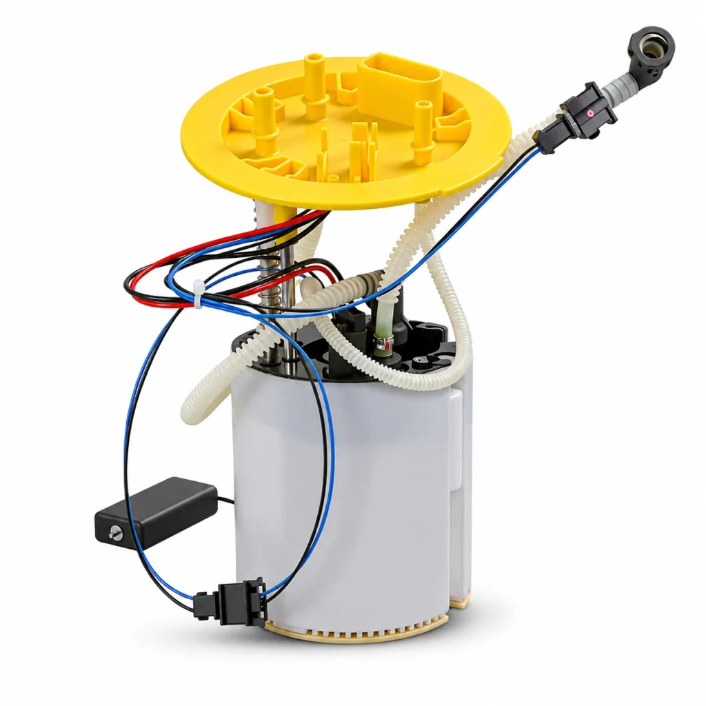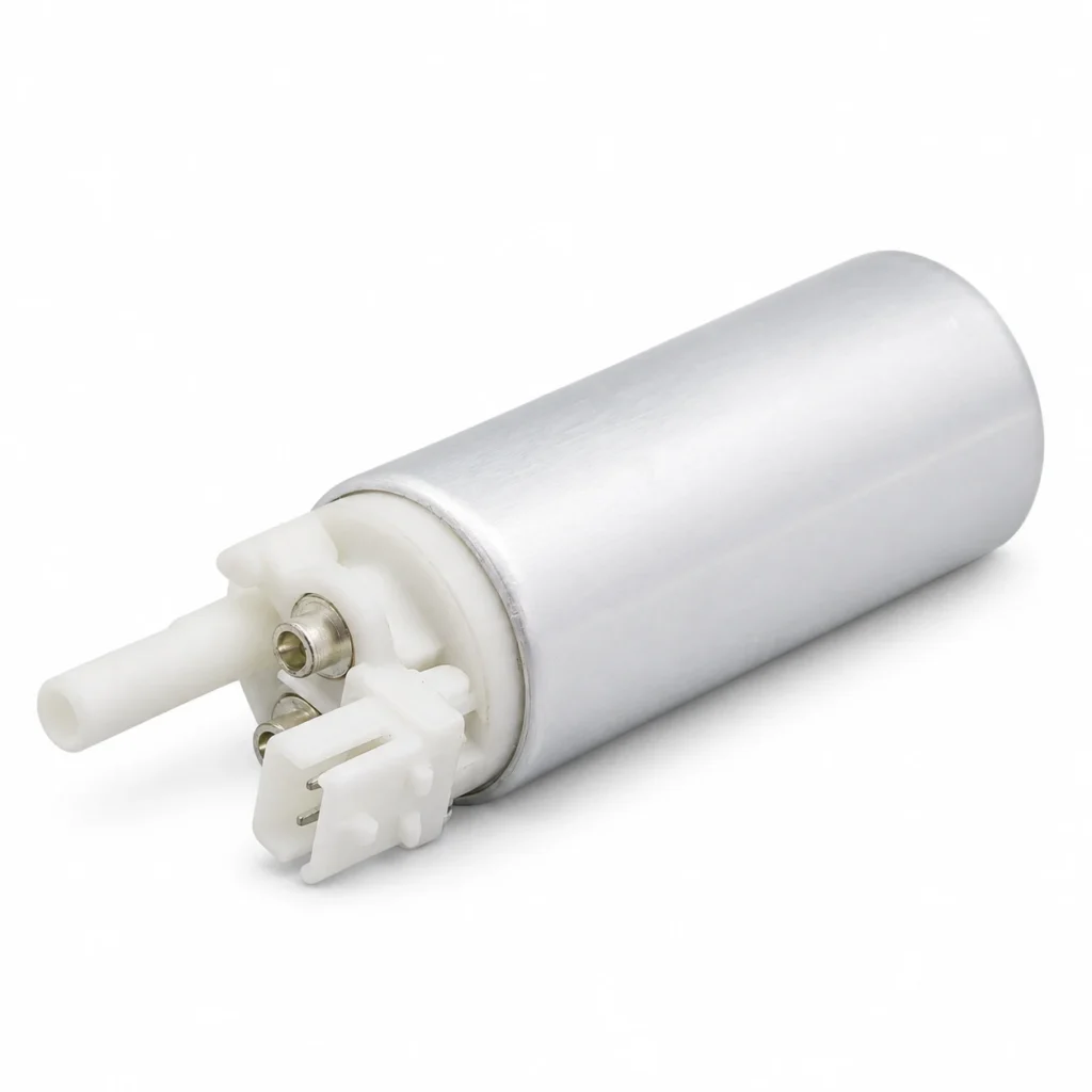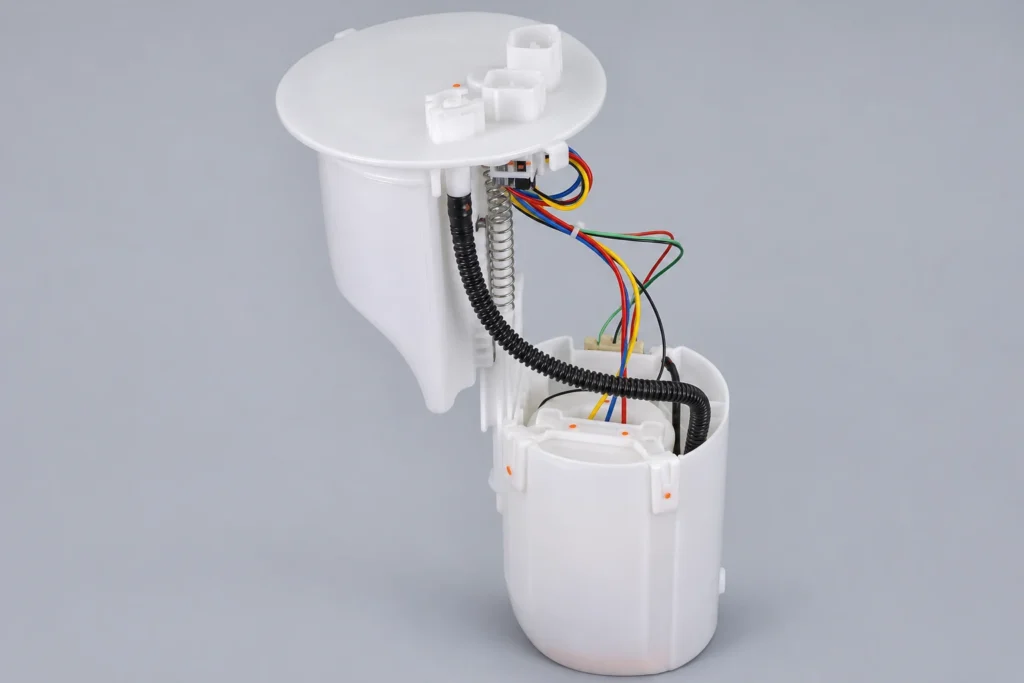
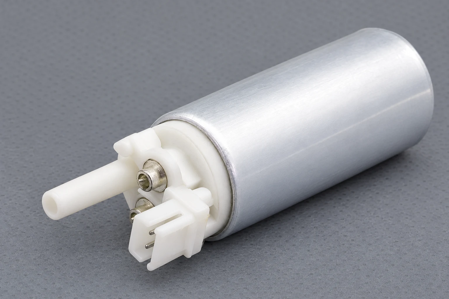
A fuel pump connector melting repeatedly usually points to concentrated electrical heating at a damaged contact, a poor termination, excessive circuit current, or a combination of these faults. Replacing the plastic plug without checking its mating terminal and the circuit load can leave the cause untouched. A fuse that remains intact does not prove the connector is healthy: a local resistive joint can overheat while total circuit current stays below the fuse’s operating threshold.
This guide focuses on finding the cause of repeat melting and documenting a durable repair. Connector identification and replacement-kit selection remain separate steps, covered in our existing linked guides.
Why a small electrical contact can produce a large hot spot
The pump circuit carries current through a series of conductors and connections. Each sound connection should add very little resistance. A loose terminal, corrosion, damaged plating, incomplete engagement, or poor crimp can concentrate resistance in a small area. Electrical energy is then dissipated as heat at that location rather than delivered to the pump.
The relevant relationships are Vdrop = I × R and P = I² × R = I × Vdrop, where current I is in amperes, resistance R is in ohms, voltage drop is in volts, and power P is in watts. OpenStax’s electrical energy and power chapter explains these resistive-heating relationships.
Consider a simplified calculation, not a pump specification: if 8 A flows through a contact with 0.10 ohm resistance, that contact drops 0.8 V and dissipates 6.4 W. If the same current passes through 0.01 ohm, the loss is 0.08 V and 0.64 W. The example holds current constant to show the effect of contact resistance; an actual pump circuit may change current as operating conditions change.
Those figures do not predict a connector’s temperature. Temperature also depends on contact geometry, materials, surrounding air or fuel, and how long the load continues. They explain why a relatively small resistance change can matter, especially when the heat is confined inside a compact housing.
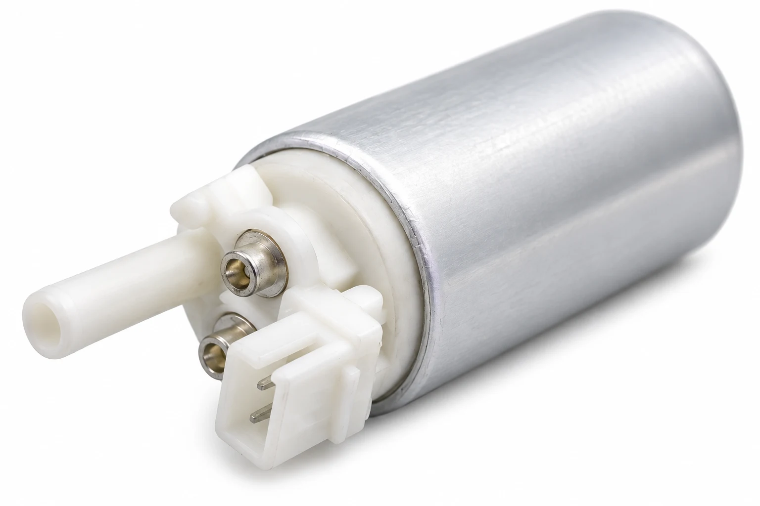
Read the damage pattern before ordering another plug
Switch off and make the fuel system safe using the vehicle’s procedure before inspection. Do not keep energizing a charred plug to see whether it still works. Document both halves of the connection, the affected cavity, nearby insulation, and any earlier repair before disturbing the evidence.
| Observed pattern | Possible explanation | Evidence to collect | Repair decision to confirm |
|---|---|---|---|
| One cavity is discolored or distorted | Localized terminal resistance or a damaged termination | Both mating contacts, retention condition, crimp area, and approved loaded-circuit results if safe | Whether both terminal halves and surrounding conductors require replacement |
| Heat damage extends along a conductor | Excessive current, unsuitable conductor or splice, or heat spreading from a joint | Wire specification, routing, splice construction, current and operating condition | Extent of harness repair and whether the installed pump matches the circuit |
| New pigtail overheats in the same position | Old mating terminal, remaining damaged wire, or unresolved circuit load | Previous repair details and a comparison with the current failure | The root cause that the previous replacement did not remove |
| Water or corrosion is present | Seal failure, incomplete engagement, or an unsuitable repair | Seal condition, lock engagement, contamination path, and conductor corrosion | How to restore sealing and prevent recurrence |
| Fuse opens as well as connector damage | A separate short or overcurrent condition may coexist | Correct fuse rating, circuit damage, pump current and fault history | Complete fault diagnosis before further operation |
This table is a diagnostic framework, not a visual pass/fail standard. It uses the heating relationships above and the loaded-circuit principle described by Fluke’s automotive voltage-drop guidance. Match the actual inspection and test criteria to the connector and vehicle documentation.
Inspect the mating side, not only the replaceable pigtail
A new vehicle-side plug can still contact a heat-damaged pin on the module flange. Distortion, damaged plating, or weakened contact retention may remain even after the visible plastic is replaced. Inspect the opposite side and any accessible internal connection using the approved service method. A housing that clicks into place does not prove the metal contact is sound.
For identification of the tank-top interface and the distinction between motor and sender circuits, use our in-tank fuel pump connector guide. Thin sender wires and pump-current conductors have different functions. Do not infer an electrical pin assignment from cavity position or insulation color alone.
Separate excessive contact resistance from excessive current
Both can produce heat, and both can exist in the same vehicle. A weak terminal can overheat at otherwise normal pump current. An incorrect or overloaded pump can expose a marginal connection to a higher load. The damage alone does not identify which happened first.
The useful evidence set combines pump current, the relevant voltage-drop measurements, and the operating condition. Measurements should be taken by a qualified technician using the vehicle’s approved access and test method, with an intact circuit that is safe to energize. A visibly melted connector may need repair before further powered diagnosis is appropriate.
Measure current with equipment suitable for the circuit, and compare it with the correct pump or vehicle specification under comparable conditions. Our electric fuel pump current guide explains why startup, pressure, voltage, and pump control matter. There is no universal current figure that clears every pump.
Loaded voltage-drop testing asks how much voltage is lost across a connection or section while current flows. An unplugged connector may show battery voltage even when its contacts cannot carry the pump load. Where a technician needs the broader circuit-check sequence, our fuel pump electrical connection guide covers that subject in more detail.
Do not compare a meter’s averaged reading on a pulse-controlled circuit with a continuous-voltage expectation without considering the control strategy. Record pump command and use the test equipment required by the procedure. Similarly, a continuity beep at very low test current does not establish that a contact will remain sound under operating load.
Why the fuse can stay intact while the connector melts
A fuse responds to current and time according to its design. It does not directly measure the temperature of a distant plug. If a poor contact creates a local hot spot while circuit current remains below the fuse’s opening behavior, the plastic can be damaged without a blown fuse.
This is why fitting a larger fuse is not a remedy for a melted connection. It changes the circuit protection and leaves contact resistance unresolved. Keep the specified protection and diagnose the heating source. A repeated fuse failure also needs its own investigation; a burnt connector should not be used to explain every electrical symptom automatically.
A temperature comparison can support diagnosis when the manufacturer’s method permits it, but a cool connector during a brief idle test does not clear an intermittent fault. Heat may depend on duration, ambient conditions, or pump duty. Record the condition under which the original melting developed and verify the repair under a safe, relevant test.
Why replacement connectors sometimes melt again
The repair stopped at the plastic housing
Replacing a shell while reusing damaged contacts leaves the electrical joint essentially unchanged. Heat may also have affected nearby insulation or conductor strands. Establish the full repair boundary from inspection and the approved harness-repair instructions, rather than cutting an arbitrary distance behind the plug.
The terminal or crimp does not match the conductor
Wire cross-section, strand construction, insulation size, terminal type, crimp tooling, and sealing system must be compatible. A crimp that looks tight from outside may still have poor conductor capture or inadequate strain support. Use the specified repair parts and method; do not improvise a generic household connector near a fuel system.
The pump or operating load changed
A higher-output replacement is not automatically compatible with the existing circuit. Confirm its intended application and electrical requirements before treating it as an upgrade. The complete path includes the controller or relay, fuse, wiring, splices, and terminals. Increasing one wire size does not establish that every remaining contact can carry the new load.
Moisture, movement, or routing damage remains
An incomplete lock, displaced seal, unsupported harness, or tension at the connector can recreate the conditions behind the first failure. Restore the prescribed routing and retention. Do not use a cable tie to force a damaged connector together or treat grease as a substitute for terminal integrity. Use only the material and application method specified for that connector system.
Verify the repair before releasing the vehicle
A successful repair needs evidence that the cause was removed. Confirm the replacement parts, cavity functions, retention, seal installation, and harness support. Then carry out the approved operational checks and compare current, voltage loss, and fuel-delivery results with the relevant specifications. Record the results so a later repeat complaint can be assessed against a baseline.
If a replacement kit is required, our fuel pump pigtail repair-kit guide covers kit scope and identification. For the pump itself, Kangsong’s C/K application electric gasoline pump catalog entry provides a specific product reference. Confirm the original part number and application details; that listing is not a universal connector repair or a solution for every melted plug.
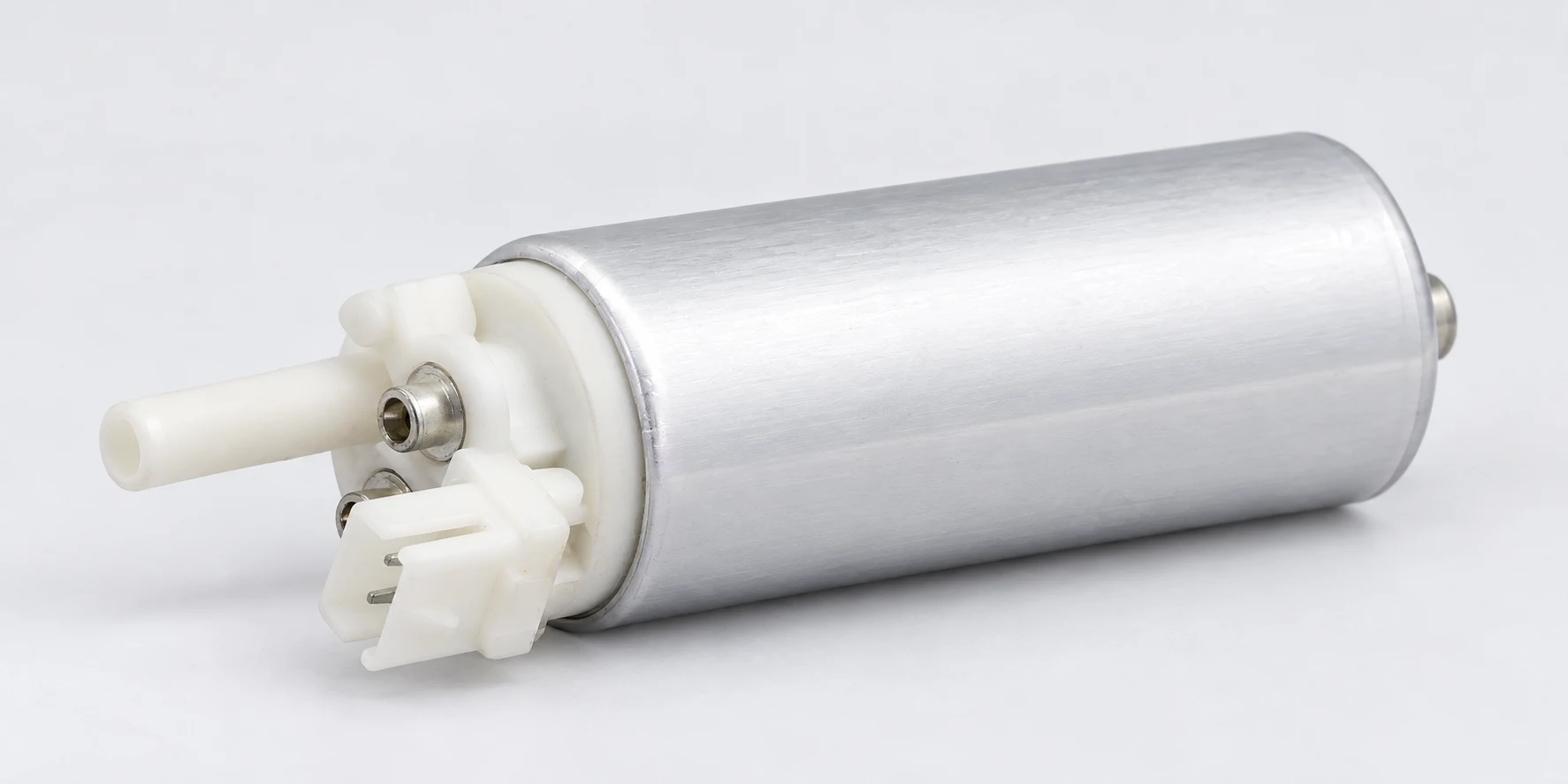
For a supplier inquiry, attach photographs of both connector halves and the original pump label. Include vehicle identification, affected cavity, wire and terminal information, previous repairs, current measurements with conditions, and the expected specification source. This helps distinguish a harness request from a pump request before another part is dispatched.
Watch: how electrical resistance becomes heat
Physics Tutoring Hub’s educational lesson explains Joule heating and the electrical-power equations used in the calculation above. It provides the physical principle, rather than a vehicle-specific repair procedure.
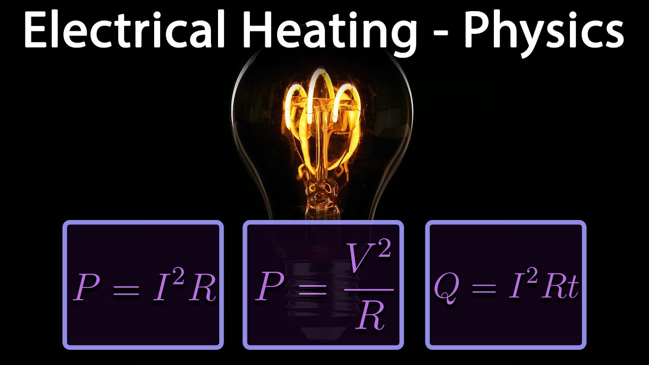
Watch Electrical Heating on YouTube.
Frequently asked questions
Can a fuel pump connector melt without blowing the fuse?
Yes. A resistive contact can create concentrated heat while the total circuit current remains below the fuse’s opening behavior. An intact fuse does not prove that the connector is sound.
Does a melted connector prove that the pump is bad?
No. The fault may be in a terminal, crimp, mating pin, harness, or circuit load. Check both connector halves and the appropriate electrical evidence before replacing the pump.
Why did the new pigtail melt in the same place?
Possible causes include a damaged mating terminal, remaining heat-damaged conductor, an unsuitable repair, or unresolved excessive current. Reassess the complete repair boundary rather than replacing the same plug again.
Can I fix the problem by installing a larger fuse?
No. A larger fuse does not repair contact resistance and can compromise the specified circuit protection. Keep the correct fuse and diagnose the cause of heating.