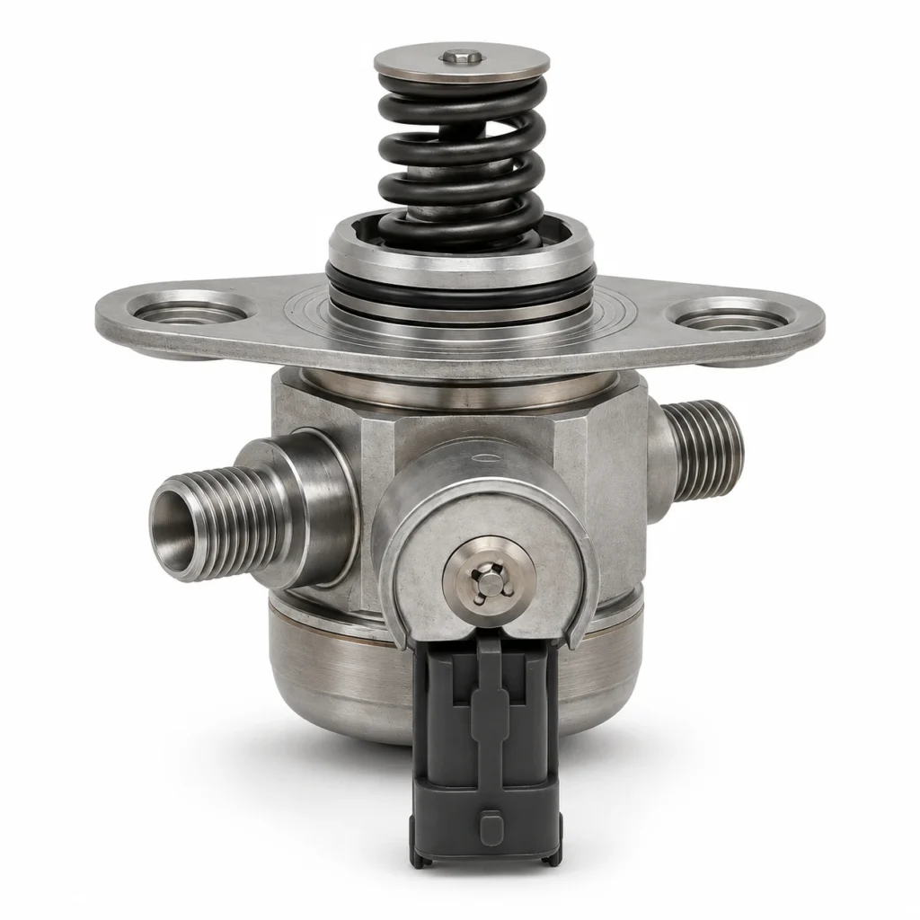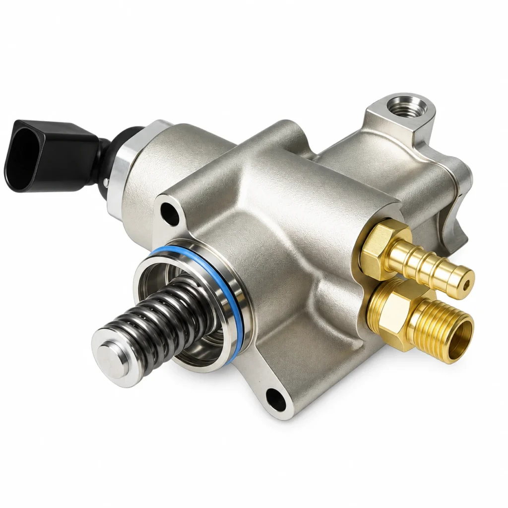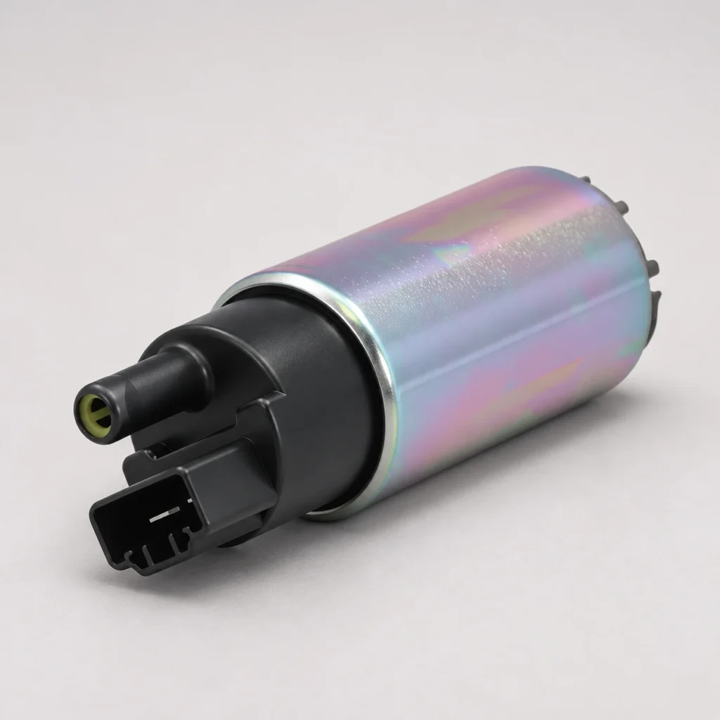
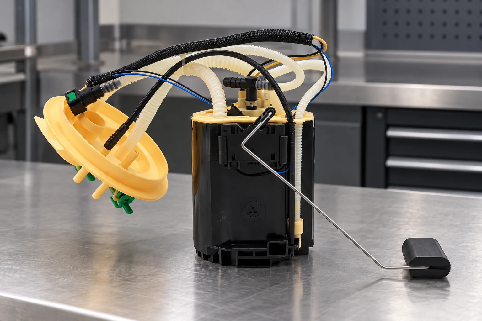
Diesel fuel pump pressure has no single correct PSI value. The right number depends on whether you are measuring the tank-to-engine supply circuit or the high-pressure injection circuit, the exact engine, the test point, and the operating condition. A low-pressure gauge reading and a scan-tool rail-pressure value describe different parts of the system. Compare either reading with the vehicle manufacturer’s procedure for that location before deciding that a pump needs replacement.
This guide helps workshops and parts buyers turn a pressure complaint into useful evidence: identify the circuit, keep the units consistent, compare commanded and actual readings, and specify the correct replacement component.
Identify the pressure circuit before looking for a number
A diesel may have a lift or supply pump that moves fuel through the low-pressure path, plus an injection pump that serves the engine’s injection system. Not every engine uses the same supply arrangement. Some draw fuel under suction through part of the inlet path; others use an electric feed pump. A pressure expectation copied from a different layout can lead to a wrong diagnosis even when the gauge is accurate.
Common-rail engines also store pressurized fuel in a rail. The rail-pressure sensor reports that circuit to the control unit. Its reading is not a measurement of the pressure coming out of the tank module. Our diesel fuel pump operation guide explains the complete fuel path; the practical issue here is choosing the correct specification for the reading in front of you.
| Pressure description | Location or evidence | Specification required | Common mistake |
|---|---|---|---|
| Low-pressure supply | The approved test point between the tank supply and injection stage | Engine-specific pressure or inlet restriction, at the stated flow and operating condition | Comparing it with common-rail injection pressure |
| Common-rail pressure | The correctly identified rail-pressure data item on a compatible scan tool | Commanded and actual values, plus the manufacturer’s allowable difference and test conditions | Treating a system maximum as the required idle value |
| Conventional injection pressure | The test method specified for that pump and injection system | Application-specific test equipment and procedure | Applying a common-rail number to a different injection design |
| Return-side condition | An approved return-flow or backpressure test point | The relevant return-system test limit | Calling a return-side reading pump outlet pressure |
The terminology matters: DieselNet’s technical introduction to diesel injection distinguishes system architectures and explains that injection pressure can refer to mean rail pressure or peak pressure during an injection event. Those meanings should not be exchanged.
Convert PSI, bar, kPa, and MPa before comparing readings
Pressure reports often arrive as photographs from different instruments. One technician records bar, another selects kPa on a scan tool, and a buyer copies PSI into an inquiry. Normalize the units before discussing a deviation. A correct number with the wrong unit can describe a completely different operating condition.
Use these conversions: 1 bar = 100 kPa = 0.1 MPa ≈ 14.504 psi. Therefore, bar multiplied by 14.504 gives approximate PSI; MPa multiplied by 10 gives bar. The NIST pressure conversion factors provide the underlying unit relationships.
For a calculation example only, 4 bar equals 400 kPa, 0.4 MPa, or approximately 58.0 psi. This is a unit conversion, not a recommended supply pressure. Likewise, 30 MPa converts to 300 bar, not 30 bar. Neither example states what a particular engine should produce.
Also identify the pressure reference. Gauge pressure is measured relative to local atmospheric pressure; absolute pressure is measured relative to a vacuum. Use the reference specified by the service procedure and instrument. Do not subtract atmospheric pressure from a scan-tool value unless its definition actually requires that conversion.
Record the operating conditions behind the reading
A pressure figure becomes useful when its context is recorded. At minimum, save the vehicle identification, engine code, fuel-system type, test location, units, operating state, and source of the expected value. Include a photograph of the instrument or a saved scan-tool trace rather than a number copied from memory.
For a no-start complaint, record battery condition and cranking speed alongside the pressure evidence required by the service procedure. Slow cranking changes the test conditions. A comparison with a warm, running engine may be misleading. Observe starter operating limits; repeated extended cranking does not replace an organized test.
For a running complaint, note whether the engine is cold or warm, at idle or under an approved load, and whether the fault occurs continuously or intermittently. A system may appear acceptable at idle and lose delivery when fuel demand rises. That does not establish which component failed, but it tells the workshop when to capture the next measurement.
On a common-rail system, save requested and actual rail pressure on the same time axis when the diagnostic tool supports it. Use the manufacturer’s expected response and tolerance rather than declaring every brief difference a failure. A screenshot that omits engine speed or units makes later comparison unnecessarily difficult.
Pressure alone also does not establish delivery capacity. A supply circuit must provide the required quantity under the specified conditions. A service procedure may call for a flow, inlet-restriction, or return-flow assessment as well. Carry out those tests only with the correct equipment and fuel-handling precautions.
What common pressure patterns can—and cannot—tell you
Supply pressure is low at the specified test point
First confirm the fuel level, fuel condition, service history, and test connection. Then follow the low-pressure diagnostic path: restricted filters or pickup, air entry, hose condition, electrical supply where applicable, pump control, and the supply pump itself. The order should follow the vehicle’s documented arrangement. Replacing the injection pump before checking its supply can leave the original problem in place.
If the problem began after filter work or running out of fuel, use the application-specific priming procedure. Our diesel supply-side priming guide covers that separate task. A recurring loss of prime requires investigation of air entry or drain-back; it should not be hidden by repeated priming.
Supply meets specification but actual rail pressure remains low
This narrows the investigation to the remaining injection-system checks; it does not prove that the high-pressure pump alone is defective. Depending on the engine, the diagnostic path can include sensor plausibility, metering and pressure control, approved injector return-flow testing, pressure-limiting behavior, and contamination assessment. A code for low rail pressure identifies a condition, not a purchase order.
Record the tests that eliminated alternatives. A supplier can assess a request more effectively when it says where the low reading occurred and what upstream evidence was obtained. The distinction between component families is explained in fuel pump versus injection pump.
Pressure is acceptable at idle but drops during the complaint
Reproduce the fault only within an approved workshop test. Check whether supply and rail-pressure changes coincide, and whether electrical pump command, engine speed, or other relevant data changed first. A synchronized record is more useful than separate readings taken several minutes apart. Avoid road testing with loose gauges, exposed fuel lines, or unsecured equipment.
The pressure reading looks implausible
Before ordering parts, confirm the selected data item, units, sensor circuit checks, scan-tool compatibility, and mechanical gauge suitability. A disconnected or damaged sensor can produce a substituted or implausible value. A basic gauge may be suitable for an approved low-pressure point while being entirely unsuitable for a common-rail connection.
Keep high-pressure testing within the approved procedure
Do not loosen common-rail pipes to look for fuel or attempt to find leaks with a hand. High-pressure fluid can penetrate skin; the UK Health and Safety Executive explains the injection hazard and the importance of correct couplings and pressure release. Its general hydraulic guidance describes the hazard, not a diesel engine test procedure.
Use the vehicle manufacturer’s shutdown, pressure-release, waiting-time, and component-replacement instructions. A stopped engine is not proof that pressure has dissipated. Where specialized high-pressure testing is required, it belongs with trained personnel and rated equipment. This guide helps interpret documented results; it does not authorize improvised connections.
Turn the result into a useful replacement request
A good inquiry separates the failed function from the component being requested. Include the engine code and vehicle identification, original part number, supply or injection stage, measurement location, expected specification source, actual reading with units, and the operating condition. Attach connector, flange, hose-routing, and label photographs where a supply assembly is involved.
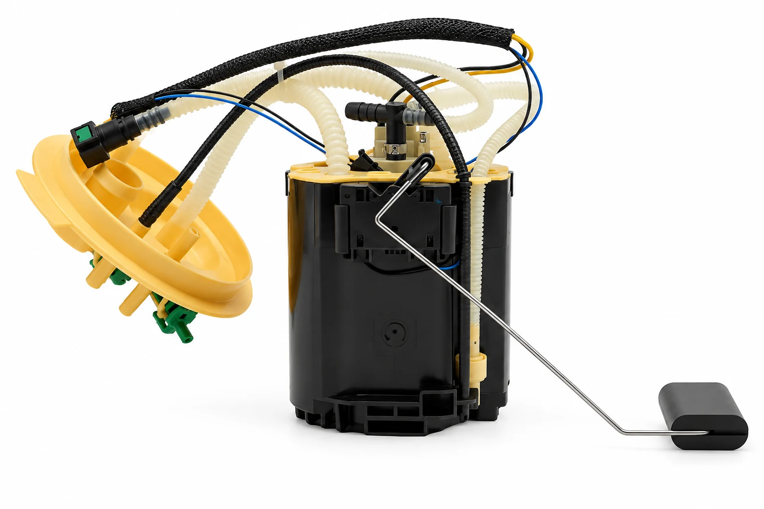
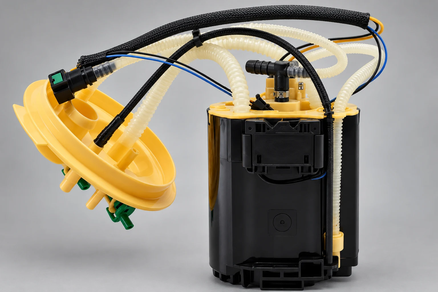
For example, the Kangsong Freelander 2 2.2 diesel supply assembly is a specific catalog entry with stated OE references. It is an identification starting point for that application, not evidence that it fits another diesel or provides a particular pressure. Confirm the vehicle’s original reference and installation details before requesting a quote.
If testing identifies the injection stage instead, begin with the high-pressure and diesel product hub and provide the exact original component information. Do not substitute a tank module for an injection pump because both names contain “diesel fuel pump.” Ask the supplier to confirm the documented match and any required installation or calibration information.
Watch: understand the two pressure stages
Engineering Explained’s educational video shows the components of a diesel common-rail system. Use it to understand where the supply pump and high-pressure pump sit; use the vehicle’s service information for actual test values.
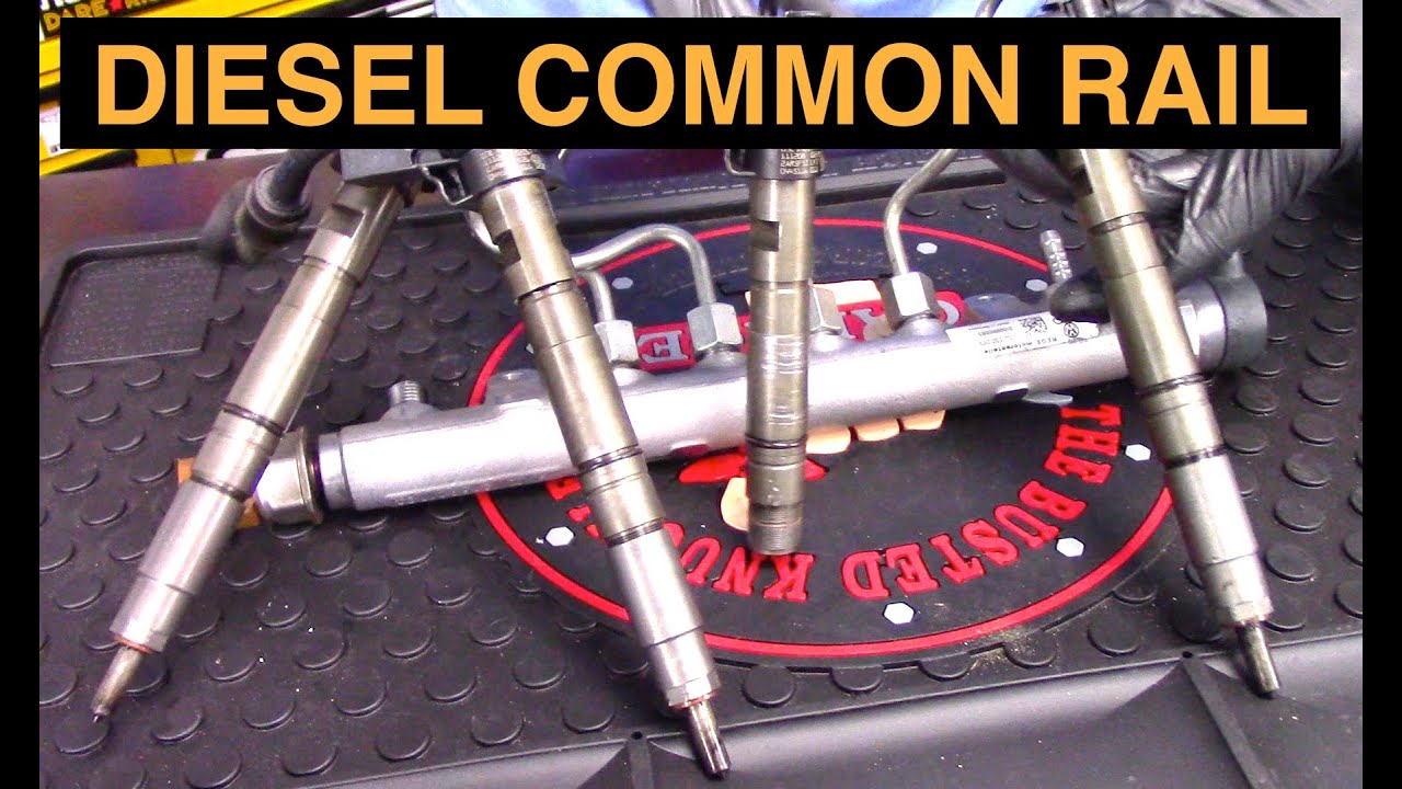
Watch How Diesel Common Rail Fuel Systems Work on YouTube.
Frequently asked questions
What PSI should a diesel fuel pump have?
There is no universal value. Identify the supply or injection circuit, engine, test location, operating condition, and units, then use the corresponding vehicle-manufacturer specification.
Does low rail pressure prove the high-pressure pump is bad?
No. Supply problems, control faults, sensor issues, and excessive leakage can also prevent the rail from reaching the required pressure. Follow the documented diagnostic sequence before replacing components.
Can a normal idle reading rule out a fuel delivery problem?
No. Some faults appear only during the reported operating condition. Compare the specified readings under the approved test conditions and include flow or restriction checks when the procedure requires them.
Is the maximum pressure in a product description the correct test target?
No. A system maximum is not an idle or cranking specification. Use the expected value for the exact application, test point, and operating state.