A high pressure fuel pump cam follower transfers motion from an engine cam to the pump plunger. If that contact is damaged, fitting a new pump alone may leave the cause of the failure in place. The correct inspection covers the follower, the pump contact surface, and the driving cam, using the procedure for the exact engine. A fuel-pressure code cannot identify which of those parts is worn. This guide explains how to organize the inspection and replacement decision without treating every gasoline direct-injection engine as the same design.
Identify the drive arrangement before ordering parts
On many gasoline direct-injection engines, an electric pump supplies fuel to a mechanically driven high-pressure pump. The engine supplies the mechanical motion; an electrical control valve regulates delivery. A pump that receives a valid command can still deliver poorly if its mechanical stroke is compromised. Conversely, a healthy drive cannot compensate for inadequate inlet fuel or incorrect pressure information.
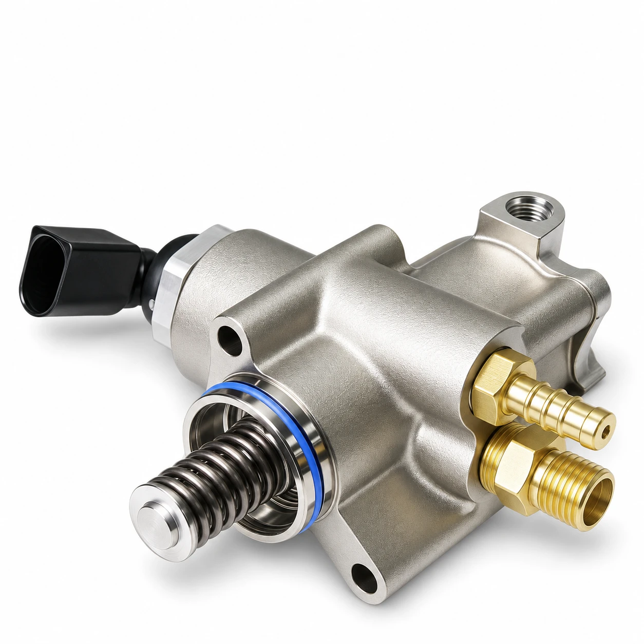
The follower is the contact element between the cam and the pump drive. Some applications use a sliding bucket or tappet; others use a roller arrangement. Those designs have different inspection details. Do not apply a flat follower’s appearance rules to a roller, or assume that an exposed spring on a catalog photograph identifies the separate follower fitted inside the engine.
Start with the VIN, engine code, production date, and installed pump number. Obtain the current service procedure and parts diagram. Confirm where the follower is located, whether it is supplied separately, and whether the pump listing includes it. A supplier’s pump photograph establishes visible configuration, not the condition or contents of an engine’s existing drive.
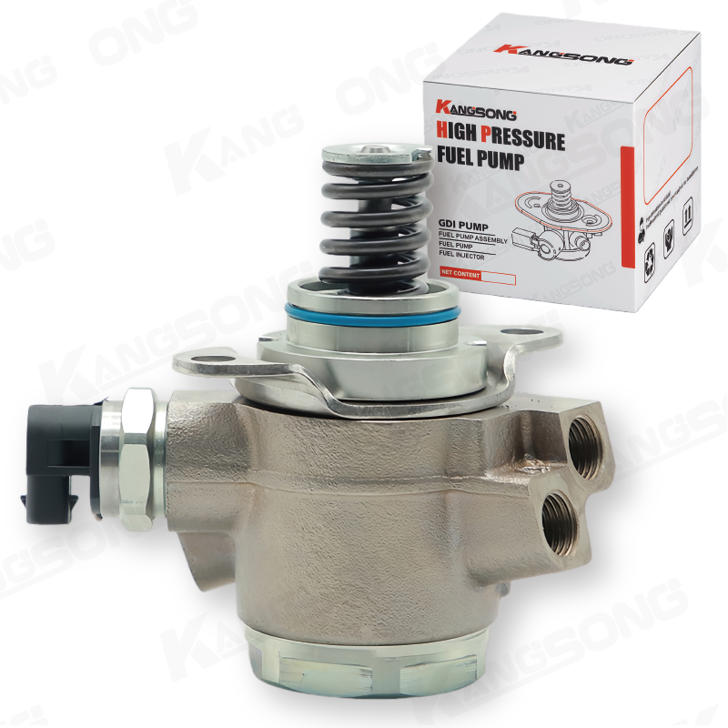
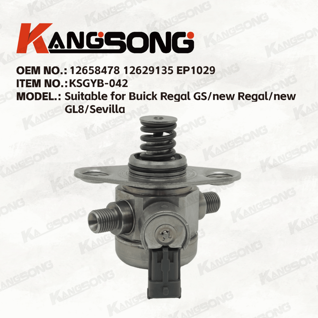
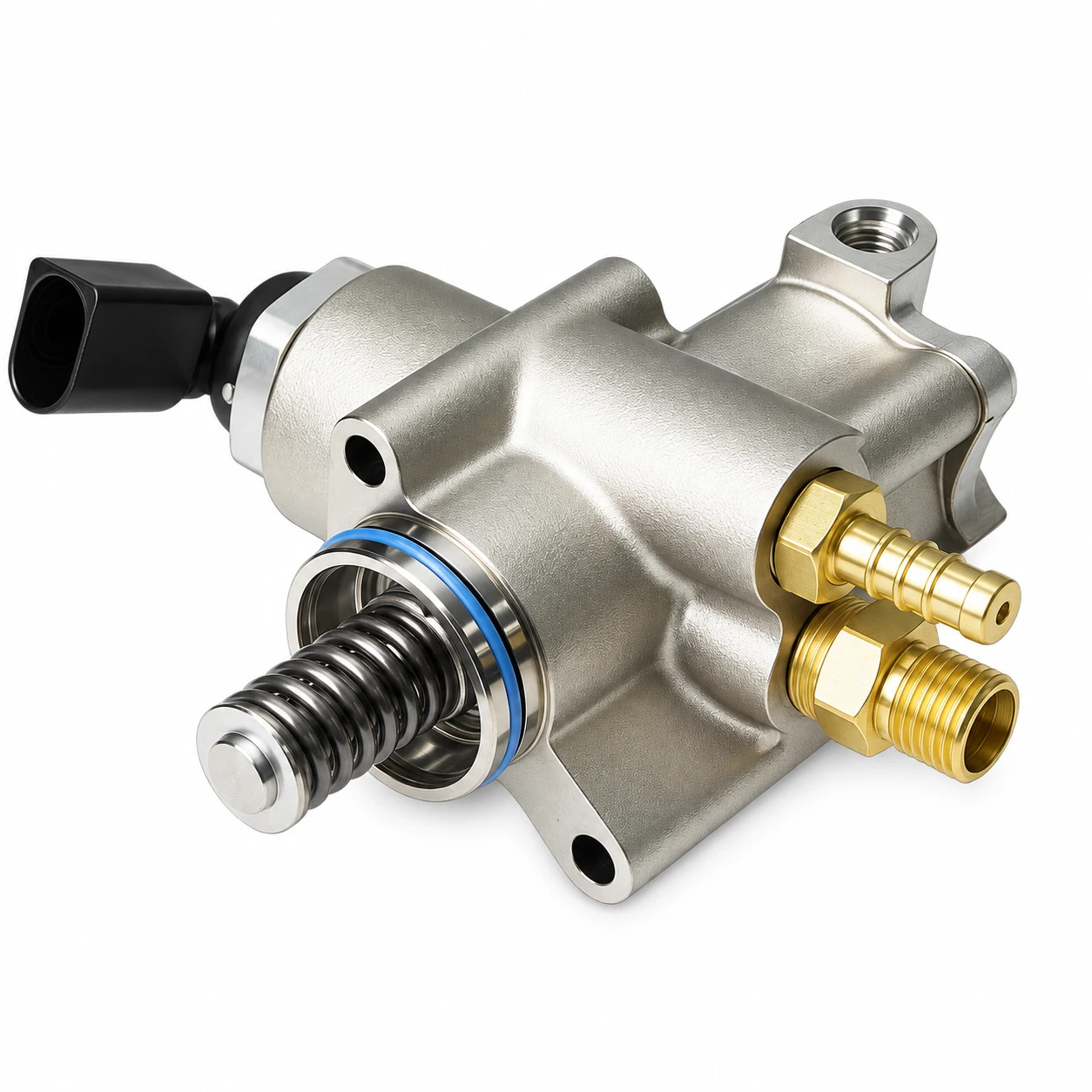
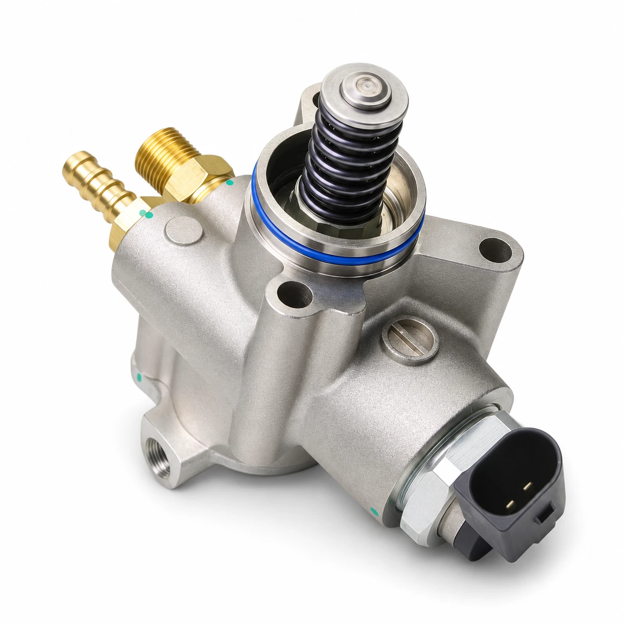
For product identification, compare the original unit with the website’s 06F127025L / 06F127025H high-pressure pump listing. Its connector, mounting flange, and fuel connections are useful comparison points. Application and supersession checks still require the vehicle’s parts information. The images here preserve the listed pump’s external form; they do not show a verified engine teardown.
Separate a pressure complaint from proof of drive wear
Reduced power, difficult starting, or a low rail-pressure fault can justify investigation, but they are not a follower diagnosis. Before disassembly, preserve fault codes and operating conditions. Compare requested and actual rail pressure, verify the low-pressure supply as directed, and inspect relevant electrical connections. Record the circumstances in which the complaint occurs rather than relying on an idle reading alone.
An engine may achieve acceptable pressure at light load while failing during another operating condition. That observation narrows the investigation but does not distinguish a supply restriction, control problem, leak, or worn drive by itself. Follow the manufacturer’s test order and avoid assigning a pump failure solely because its name appears in a diagnostic-code description.
This article concerns the gasoline pump’s mechanical interface. The site’s high-pressure and diesel product hub separates the relevant product families. The diesel fuel pump pressure guide discusses different test-point boundaries; its values should not be transferred to a gasoline application.
Make pressure relief and engine position part of the job
High-pressure gasoline can remain hazardous after the engine stops. Opening a connection to see whether pressure remains is not an acceptable test. Use the manufacturer’s pressure-relief procedure, required equipment, and confirmation steps before removing the pump or pipe. Keep ignition sources away and contain fuel using equipment intended for fuel service.
The Kia GDI service bulletin documents special precautions for high-pressure system work. Its procedures illustrate why GDI repair requires application-specific handling. They are not universal instructions for every pump pictured on this website. Pipe reuse, sealing parts, tightening sequence, and torque must come from the correct vehicle procedure.
Cam position also matters because the pump may be under spring load. A procedure can specify a particular crankshaft position for removal or installation. Copying a crank angle from another engine can create the wrong installation condition. A pump that resists seating should trigger a review of alignment and cam position, rather than an attempt to force it down with the mounting bolts.
Inspect the complete contact path
After safe removal, protect the open fuel connections from contamination. Keep removed components organized and photograph their position before cleaning changes the evidence. Inspect the follower’s contact area, the pump’s contact end, and the cam surface using the access and rotation method specified by the manufacturer. One polished spot is not enough information to classify the whole drive.
A Honda service bulletin hosted by NHTSA includes inspection of the pump-driving cam for damage during its specific repair. That is a useful example of checking the driving component as well as the pump. It does not establish an inspection interval or wear limit for other engines.
For a roller design, inspect the roller and its supporting arrangement according to service information. For a sliding follower, use the specified criteria for the contact face and coating. Document pitting, scoring, abnormal shape, restricted movement, or missing material without inventing an allowable depth. Where the manual calls for measurement, visual judgment cannot replace that measurement.
Use an inspection record to decide repair scope
| Inspection finding | What it establishes | Next decision |
|---|---|---|
| Drive components satisfy the vehicle’s inspection criteria | No rejection condition was found in the inspected contact path | Continue the prescribed fuel-supply and control diagnosis |
| Follower damage with uncertain cam condition | The contact interface needs further evaluation | Complete cam inspection before releasing a pump-only order |
| Cam damage or missing follower material | The repair may extend beyond the pump | Determine mechanical repair and contamination handling from service information |
| Different drive or mounting configuration on the replacement | The proposed part has not passed identification checks | Stop installation and resolve the application or supersession |
| Pressure complaint remains after mechanical inspection | The inspected drive alone does not explain the complaint | Return to the documented hydraulic and electrical test path |
This is a decision record, not a substitute for an engine-specific repair manual. The manufacturer’s rejection criteria determine which parts may remain in service. A follower can be relatively inexpensive compared with a camshaft repair, but price alone is not a valid reason to reuse a damaged mating component or replace an undamaged one.
If material is missing, ask where it may have travelled and what the manufacturer requires next. Do not label an oil change as complete contamination removal without supporting instructions. Likewise, do not assume that debris found near the drive proves contamination throughout the fuel rail. Distinguish the lubricated mechanical side from the fuel side and investigate each affected path separately.
Prevent a repeat failure during installation
Before assembly, resolve the original cause and confirm that all required parts are available. Check the replacement pump’s mounting pattern, connector orientation, inlet and outlet type, and drive interface against the approved reference. Keep transport protection in place until the connection is ready to be made. Cleanliness is especially important around small control passages and high-pressure sealing surfaces.
Use the specified lubrication only where instructed. Do not coat fuel sealing seats, electrical terminals, or other surfaces merely because the follower requires lubrication. Replace designated single-use pipes, seals, clips, or fasteners as the procedure requires. A line that can physically be screwed back on has not thereby passed a reuse assessment.
After installation, carry out the prescribed priming and leak checks before returning the vehicle to service. Recheck the original complaint under permitted conditions and compare the new data with the saved baseline. Clearing a code and observing a smooth idle does not establish that the previous load-related pressure fault is gone.
For a separate electrical supply complaint, see the fuel pump connector melting guide. That fault belongs to another part of the system and should not be treated as proof that a mechanically driven pump’s follower has failed.
What a distributor should include in the order
A useful order includes the VIN, engine code, original pump number, approved replacement number, installation position where applicable, and photographs of the removed unit. Add the follower inspection result and any required associated parts. State clearly whether the request is for the pump, a follower, or a complete repair package; those are different supply scopes.
Ask for written clarification of included seals and accessories. A product picture may contain packaging or show a spring-loaded drive without showing every supplied service part. Preserve the inspection report with the order so that an additional camshaft repair is not discovered only after a pump-only shipment arrives. For fleet purchases, retain the same evidence for each vehicle rather than assuming every engine in the fleet shares the same revision.
Further learning: cam and follower motion
IIT KANPUR-NPTEL: Lecture 43 : Cam and Follower Design
The IIT Kanpur NPTEL lecture explains cam-and-follower motion as a mechanical principle. It helps explain why the mating surfaces matter, but it is not a fuel-system disassembly demonstration or a source of vehicle repair specifications.
FAQ
Does a low rail-pressure code prove that the follower is worn?
No. The code reports a system condition. Supply, control, leakage, pressure measurement, and mechanical drive faults must be distinguished using the correct diagnostic procedure.
Should every high-pressure pump receive the same follower?
No. Follower design and supply scope vary by engine. Confirm the parts diagram, current service information, and exact replacement application before ordering.
Can a new pump fix a damaged camshaft contact surface?
A new pump does not restore a damaged mating surface. The complete contact path must meet the manufacturer’s requirements before the repair is released.
Is there one inspection mileage for all gasoline high-pressure pumps?
No universal interval is established here. Use the maintenance instructions, service bulletins, and diagnostic findings that apply to the particular engine and vehicle.