If the fuel gauge is wrong after fuel pump replacement, check the replacement module, float movement, sender connection and installation orientation before condemning the dashboard. A working pump motor does not prove that the level-sensing part of the assembly is correct. Record whether the reading is stuck, consistently offset, or slow to change, and compare that pattern with the vehicle’s service information. Do not assume that disconnecting the battery will repair a trapped float or an incompatible sender. Until the reading is reliable, avoid using the gauge to judge how far you can travel.
Separate the pump’s two jobs
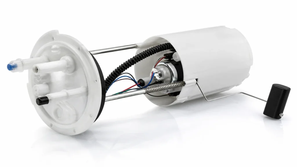
An in-tank assembly can contain both the motor that delivers fuel and the sender that reports tank level. These functions share a housing but need separate evidence. A vehicle may start and drive normally while its gauge remains inaccurate. Conversely, an engine that stops with a nonempty gauge may have a delivery problem, an incorrect level indication, or a tank-transfer problem.
The Government Engineering College Wayanad fuel-float explanation describes the relationship between the float, arm and variable resistor. That is useful background for conventional float senders; it is not a wiring diagram or calibration specification for every vehicle. Some systems combine more than one sender and process the signals before displaying a level.
For broader parts identification, see our fuel pump assembly overview. The important distinction here is between fuel delivery and fuel measurement. Ask which function failed its test, rather than accepting a diagnosis that simply says “bad assembly.”
Start with the history, not another removal
Write down the reading before the repair, the fuel quantity added afterward, the vehicle’s parking angle, and whether the complaint appeared immediately. Record the old and new module numbers, including suffixes, and whether the original sender or float arm was transferred. These details can identify an installation or specification mismatch before the tank is opened again.
Check the correct model, engine, tank and drivetrain configuration. Similar-looking modules may have different arm geometry, sender characteristics or internal arrangements. A matching connector shell alone is not sufficient. If a replacement was selected using a broad vehicle description, have the supplier confirm the exact application and reference number before further work.
Do not repeatedly fill the tank beyond the vehicle’s normal fueling instructions to force the needle to full. Refueling observations are evidence, not a reason to overfill. If there is fuel odor, visible wetness or a separate drivability concern, address that condition before treating this as an isolated gauge complaint.
Use the pattern to choose the next check
The following table organizes inspection priorities. It gives no universal resistance values, pin numbers or waiting periods because those depend on the vehicle. A pattern suggests a test; it does not establish the failed component.
| Observed pattern | Evidence to collect | Inspection priority |
|---|---|---|
| Reading changed immediately after module installation | Old/new references, installation notes, scan data | Application match, float clearance and connector seating |
| Gauge stays at one end of the scale | Stored level-circuit faults and sender signal | Circuit integrity using the correct wiring diagram |
| Reading moves but never reaches full | Actual refill history and sender travel | Float restriction, hose interference and tank condition |
| Reading jumps over bumps | Reproducible signal interruptions | Terminals, harness routing and intermittent sender faults |
| Scan level changes but the display disagrees | Simultaneous sender data and dashboard observation | Display processing or communication diagnosis |
| Vehicle runs out while gauge indicates fuel | Delivery evidence and individual tank-side levels where applicable | Distinguish level measurement from transfer or supply faults |
Two manufacturer examples show why mechanical checks matter. GM bulletin PI0658 describes float-arm restriction on specified vehicles. GM bulletin PI1192 describes internal hose routing that interferes with a sender on specified Captiva Sport models. These are bounded examples, not evidence that either defect exists in the vehicle being inspected.
Inspect installation clearance without bending the evidence
If the service procedure calls for removal, a trained technician should make the fuel system safe and remove the assembly using the specified equipment. Photograph the module orientation and connections first. Once removed, check that the float is attached, the arm follows its intended path, and no hose or harness lies in the sweep area.
Avoid bending the arm to make the dashboard agree with an assumed fuel quantity. An improvised bend can hide the original fault, change the useful travel, or create a second interference point. Compare the removed part with an exact approved reference and use only the adjustment method, if any, authorized for that application.
A sender may move freely outside the tank yet touch a baffle after installation. Module clocking, compressed height, tank deformation and routing therefore need consideration together. Verify the installed position specified in the manual rather than treating free bench movement as a complete acceptance test.
Protect the level mechanism during handling. Do not rest the assembly on the float arm or lift it by the wiring. Preserve the old part long enough to compare the mounting points, arm shape and connector arrangement. A clear before-and-after comparison is more useful to a supplier than photographs taken after the suspect arm has already been modified.
Test the sender circuit with application-specific limits
Retrieve and save fault codes before clearing anything. Where scan data is available, compare the sender input or calculated level with the dashboard indication. Identify whether the displayed value represents one sender or the combined result of several inputs. A generic scanner may not expose all the information needed for this distinction.
Use the manufacturer circuit diagram to identify the level circuit. Do not bridge terminals based on wire color or confuse the motor feed with the sender signal. Resistance checks belong on an appropriately isolated circuit according to the service procedure; a meter reading from an energized or connected network can be misleading and may risk damage.
If the specified test includes moving the float through its travel, record both endpoints and the behavior between them. An acceptable endpoint does not rule out an interruption in the middle. Equally, resistance increasing rather than decreasing is not automatically wrong: the required direction and range come from the exact sender specification.
For disturbed terminals and connector handling, our fuel-pump wiring-harness guide provides related context. Keep the diagnostic record specific to the level circuit; a satisfactory motor power test does not clear a separate sender connection.
Decide whether a reset is actually required
Some vehicles have a defined calibration, initialization or display update process. Others do not require a special reset after a correct module installation. Follow the current vehicle procedure rather than a universal key-cycle sequence found online. A reset cannot free a mechanically trapped float, restore a broken connection or make the wrong resistance characteristic correct.
If the service information requires a known fuel quantity or a particular vehicle attitude for calibration, meet those conditions and document them. Do not infer success solely because the needle moved after a battery disconnect. Confirm that the level remains plausible at the next meaningful change in fuel quantity and that the original complaint no longer occurs.
This Boating Zen educational video illustrates the basic relationship between a conventional tank sender and its gauge in a marine application. Use it for that shared measurement principle only. Its test connections and component values must not be transferred to an automotive system; obtain the vehicle’s wiring diagram and approved test method.
Boating Zen: Trouble shooting Fuel Tank gauge, sender
Build a useful supplier inquiry
For an assembly inquiry, send the vehicle identification and original reference, tank variant, new module marking, connector photographs, and the measured sender results with the test conditions. State whether the engine’s delivery function is satisfactory. This prevents an inaccurate gauge from being reported as a pressure or flow failure without supporting evidence.
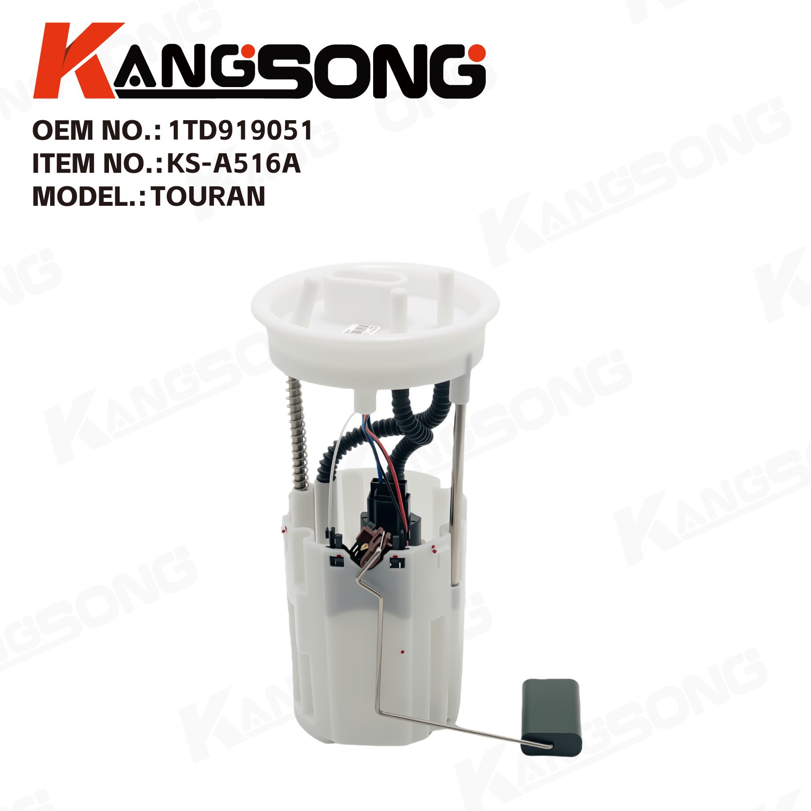
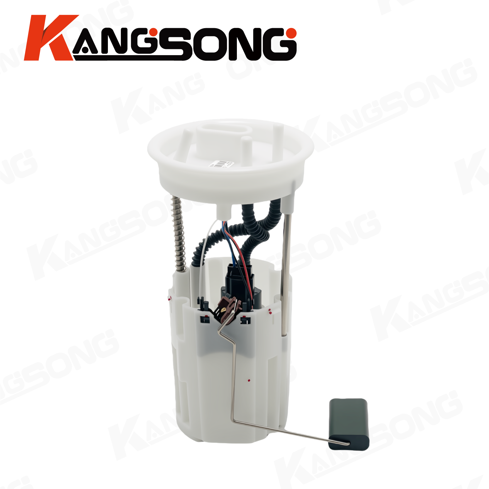
The 1TD919051 reference fuel-pump assembly illustrates a module with a visible float arm. Its appearance helps explain the parts being discussed; it does not establish sender resistance, tank compatibility or suitability for another vehicle. Confirm those requirements against the requested application before ordering.
When deciding the repair scope, compare a separately serviceable sender with a complete assembly only where the parts catalog permits both. Include disturbed seals and retainers required by the service procedure. For that purchasing distinction, see fuel pump assembly versus pump motor. Replacing more components is not a substitute for locating the actual fault.
Verify the repair in the vehicle
After reassembly, the workshop should complete the prescribed seal and leak checks before closing access areas. Confirm that connectors are locked, hoses follow the specified path, and no level or communication faults remain unresolved. Record the actual fuel quantity information available rather than declaring an exact tank percentage from the needle alone.
Compare scan information and the dashboard under the same conditions used to document the complaint. If the original issue appeared only after refueling or over a particular part of the gauge range, one stationary observation is insufficient. Plan a safe follow-up that can confirm that range without deliberately running the vehicle dry.
A useful completion report states what was found, what was corrected, and what was measured afterward. For example, “hose interference corrected; sender travel and displayed response checked under the manual’s conditions” communicates more than “gauge reset.” If evidence remains incomplete, say which operating condition still needs verification.
FAQ
Can the pump work while the fuel gauge is wrong?
Yes. The delivery motor and level sender perform different functions even when they share one assembly. Verify them separately.
Will disconnecting the battery fix the reading?
It cannot repair a trapped float, damaged connection or incorrect sender specification. Use a reset only when the vehicle procedure requires it.
Should I bend the float arm until the gauge reads full?
No. Preserve the original geometry and follow the approved inspection or adjustment procedure. An improvised bend can create a new error.
Does every sender use the same resistance range?
No. Obtain the exact specification for the vehicle and sender. Matching connector shape or module appearance does not establish electrical compatibility.