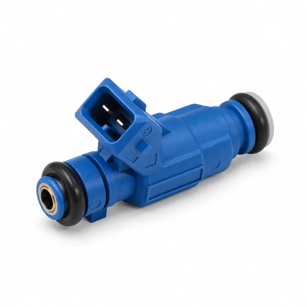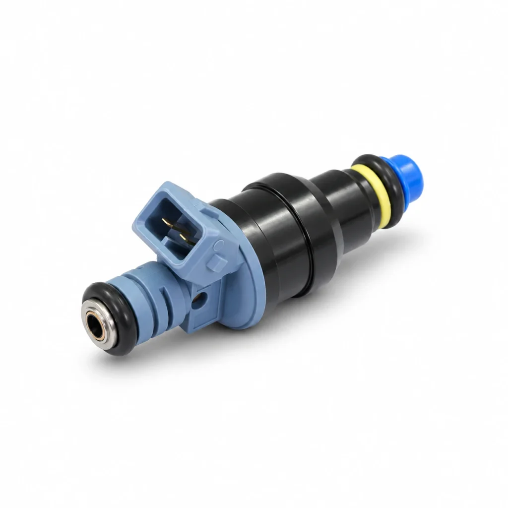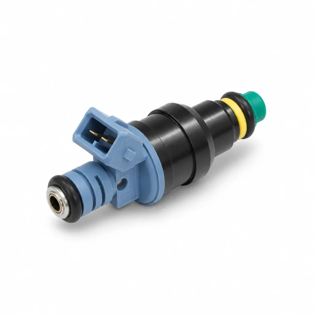
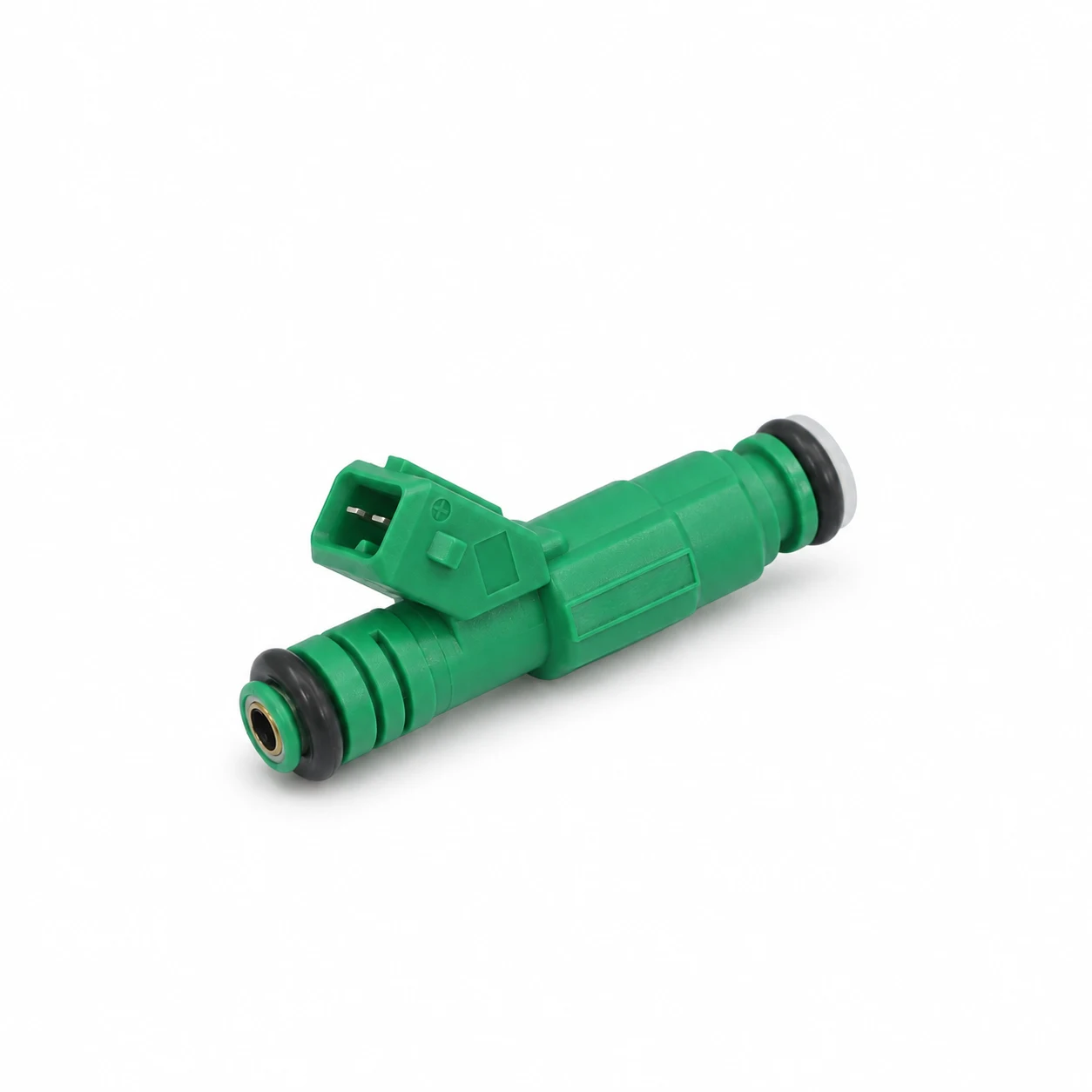
High impedance fuel injectors have an electrical coil intended to work with a compatible injector driver, commonly a saturated driver in port fuel injection systems. “High impedance” does not mean high flow, higher fuel pressure, or universal ECU compatibility. A correct replacement must match the electrical driver, physical installation, fuel requirements, and calibration data. For buyers and workshops, the useful question is not whether two injectors look alike, but whether the proposed part has documented compatibility with the original system.
This guide focuses on conventional solenoid port injectors. Do not transfer its driver assumptions to gasoline direct injection, diesel common rail, or piezoelectric systems, which require their own specifications and procedures.
What impedance tells you about an injector
An injector coil has resistance and inductive behavior. Workshop literature often uses the term impedance when classifying injector families, while a handheld ohmmeter measures DC resistance. These ideas are related, but a resistance measurement alone does not describe the complete current waveform, opening delay, or response to a driver.
In a saturated arrangement, the driver switches the injector circuit for the commanded event and coil resistance limits the eventual current. In a peak-and-hold arrangement, the driver manages an initial opening current and then a lower holding current. The appropriate strategy follows the injector and ECU specifications; the operator should not choose it simply to make an engine start.
Haltech’s injection staging documentation explicitly distinguishes saturated operation from current-controlled modes and requires supplier data for custom settings. Its example settings belong to that ECU environment. They are not universal limits for every injector sold as high or low impedance.
Why a resistance range is not an interchange rule
Generic resistance ranges are useful for orientation, but a part should be judged against the correct manufacturer’s specification at the stated temperature. Different manuals may classify borderline values differently. A seller’s broad “high impedance” label does not replace an exact part number, resistance tolerance, or approved driver requirement.
Compare measurements taken under equivalent conditions. A hot coil should not be judged against a cold specification without the required correction or test method. Test-lead resistance and poor terminal contact also matter, especially when a small difference is being used to make a decision. Document the instrument, temperature, and actual reading rather than reporting only “passed.”
An open coil or a value outside the specified limits is evidence requiring investigation. A reading within range is narrower evidence: it says the static coil resistance met that particular check. It does not prove a clean nozzle, correct flow, tight sealing, or consistent behavior during short injection events.
Match the ECU driver before connecting the injector
Begin with the exact ECU model or original application and its approved injector type. Then identify any external resistor pack or intermediate driver already present in the harness. A previous modification may have changed the electrical arrangement, so the vehicle model alone is not always enough to identify what is now installed.
Using a low-resistance injector on a driver intended for a different load can create excessive current or trigger protection. Conversely, adding resistance where it is not specified can change opening behavior. Do not remove or install a resistor pack based on a generic online conversion instruction. Follow a complete, documented combination of injector, harness, driver, and calibration.
The number of injectors connected to each output also matters. Two injectors wired together do not present the same load as one injector. A controller that supports a particular injector individually may impose different limits when outputs are shared. Obtain the allowed arrangement from the ECU manufacturer rather than extrapolating from a connector count.
| Selection question | Evidence to request | What appearance cannot establish |
|---|---|---|
| Will the driver operate this injector? | Coil specification, driver mode, approved load and resistor-pack arrangement | Electrical suitability from color or connector shape |
| Will it fit the rail and manifold? | Dimensional drawing, sealing dimensions, retention and connector clearance | Correct installed length from a similar photograph |
| Will it deliver the intended fuel? | Flow and leakage results with test fluid, differential pressure and conditions | Flow rate from impedance classification |
| Will the ECU meter it accurately? | Validated characterization data for the intended ECU and application | Correct opening delay from a static resistance result |
| Is it suitable for the fuel? | Documented fuel and material compatibility | Ethanol or alternative-fuel approval from an OE-style housing |
The table separates independent acceptance decisions. An injector can satisfy one row while failing another. Close each relevant question before approving a substitute for a production vehicle or a wholesale order.
Electrical fit does not establish fuel delivery
Two injectors can share a driver class and still differ in flow capacity, spray targeting, sealing arrangement, connector keying, and installed height. They may also require different calibration data. Treat an impedance match as one filter in the selection process, not as the final compatibility decision.
When comparing flow information, obtain the pressure difference across the injector, the test fluid, and the reporting units. A number quoted under different conditions is not automatically comparable. Keep mass and volume units distinct unless the necessary fluid data and conversion conditions are known. Avoid choosing a replacement from a single unlabeled flow figure.
Fuel supply problems can also confuse an injector diagnosis. Pressure outside the application’s requirements changes the conditions under which fuel is delivered. If the symptom involves starting after a hot or extended soak, review the separate possibilities discussed in fuel pressure loss after shutdown rather than assuming an injector electrical fault.
Check resistance safely and preserve useful evidence
Use the vehicle manufacturer’s isolation and access procedure. Resistance testing requires an unpowered, appropriately disconnected circuit; do not place an ohmmeter across an energized injector. Work around fuel connections only with the specified pressure-relief and fire precautions. There is no need to open a pressurized fuel system merely to identify an electrical connector.
Inspect connector condition and use suitable contact methods that do not spread terminals. Record the reference specification alongside each reading. Where comparison among cylinders is part of the approved procedure, take readings at comparable temperatures and investigate meaningful differences rather than selecting an arbitrary universal tolerance.
Fluke’s injector measurement guide explains the distinction between resistance and pulse-width checks. Neither check should be treated as a complete hydraulic test. Stop when the procedure requires equipment or specifications that are unavailable, rather than improvising a battery-powered injector test near fuel.
Use voltage and current together when diagnosis requires it
An oscilloscope can show what happens during the injection event rather than only a static coil value. Voltage records the switching behavior at the chosen measurement point; current records the electrical load response. Their relationship can help distinguish a missing command from an open load or another circuit problem, when interpreted against the correct reference.
A connector pulse is not proof that the injector delivered the required fuel. Likewise, a clicking sound is not a calibrated flow or leakage measurement. Electrical and hydraulic results should support each other, and the final test should correspond to the complaint. A fault that appears only hot needs evidence under those conditions.
Snap-on’s voltage and current testing demonstration illustrates complementary electrical observations. Use the vehicle’s specified connections and appropriate instrument ratings. Injector turn-off events can produce voltage transients, and generic probe settings should not be copied across different injection systems.
What to ask KANGSONG before ordering
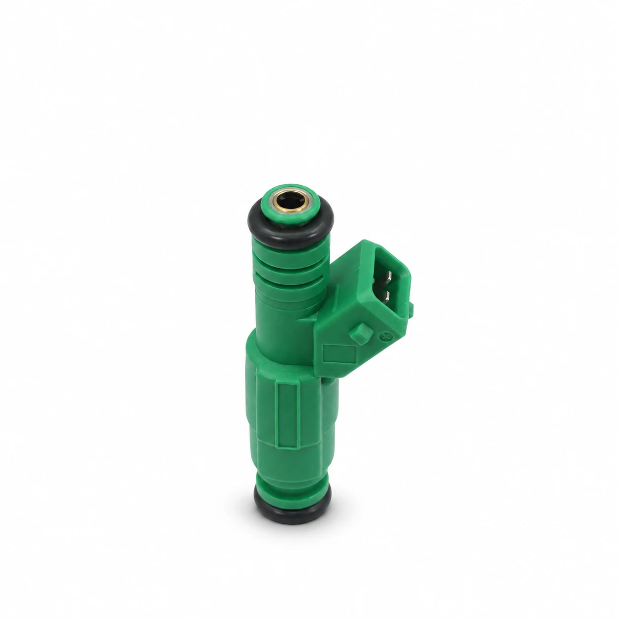
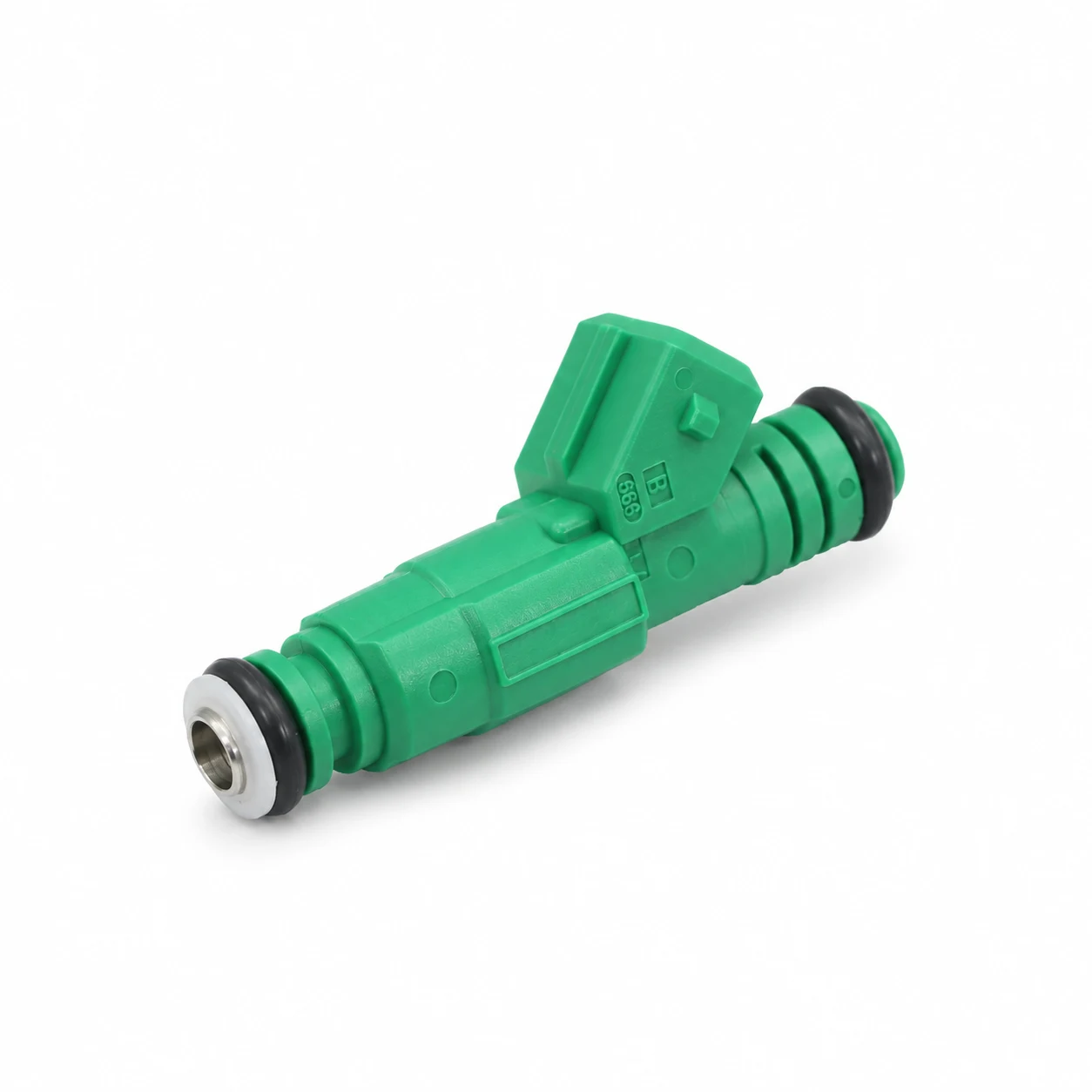
Start with the original part number and complete application details, including engine version and any ECU or harness changes. Provide clear photographs of the original component and connector, but also request dimensions and electrical specifications. Photographs help identify a candidate; they do not replace technical confirmation.
The KSP0371 injector listing referencing 0280155930 is an example of a product page from which to begin an inquiry. Its published application information and appearance do not independently verify a high-impedance classification. Ask for the exact supplied part’s resistance specification, driver suitability, flow conditions, and compatibility evidence.
For a sample order, agree on the acceptance criteria before testing. Specify sample identification, electrical checks, leak and flow requirements, test conditions, and the required report format. Keep the supplier’s part revision linked to the approved sample so that later shipments can be checked against the same definition.
For broader system planning, our automotive component range provides a starting point. Injector selection should remain coordinated with the fuel supply system. The fuel pump capacity guide addresses a different component’s delivery role, while E85 fuel-system compatibility checks explain why a fuel change requires documented suitability beyond one part.
Further learning: interpreting injector waveforms
ScannerDanner’s educational introduction below covers voltage and current patterns and different injector driver designs. It helps explain why electrical classification matters. It is supplementary training, not a substitute for the specific injector, ECU, and vehicle documentation needed for a repair.
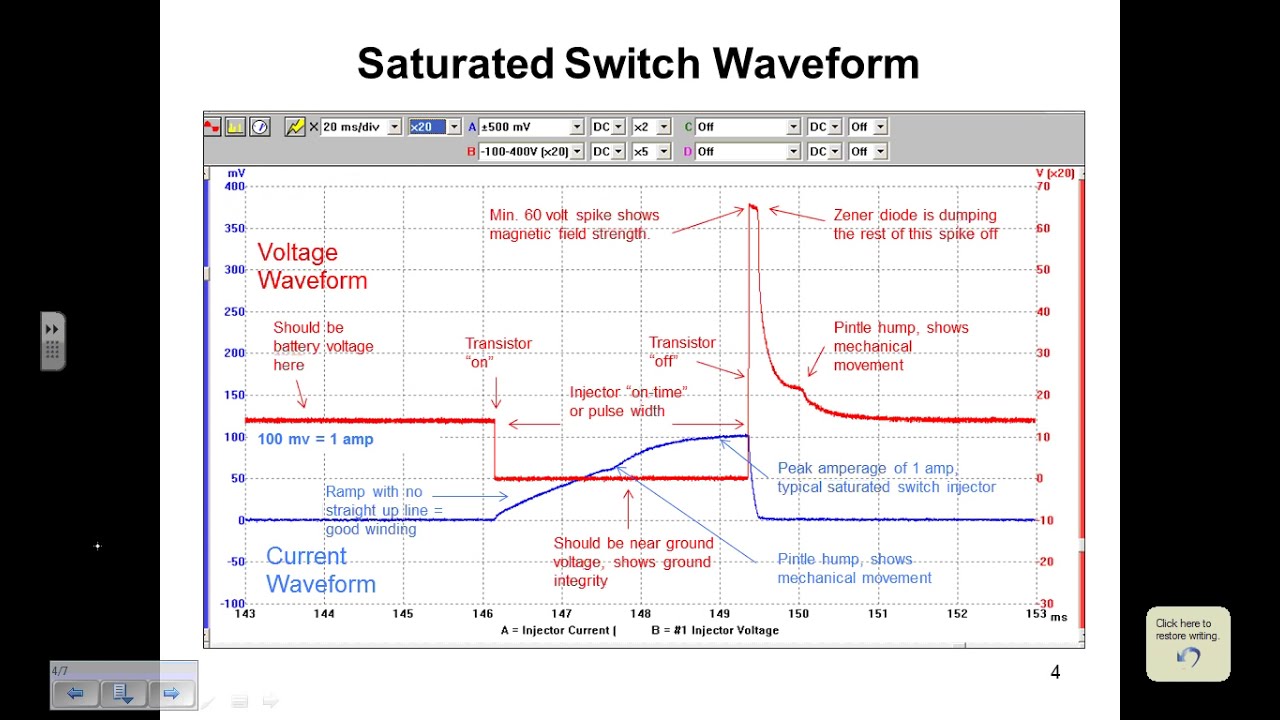
Watch ScannerDanner’s injector waveform introduction on YouTube.
Frequently asked questions
Does high impedance mean a higher-flow injector?
No. Impedance describes electrical behavior, while flow describes fuel delivery under defined conditions. Request both electrical specifications and hydraulic characterization before comparing replacement options.
Can I identify injector impedance from its color?
No. Color and external shape are not sufficient evidence. Identify the exact part and obtain its coil specification, then use the approved resistance test if verification is required.
Can a high-impedance injector replace a low-impedance one?
Only when the complete combination of ECU driver, harness, resistor arrangement, physical fit, fuel suitability, and calibration is documented as compatible. A matching connector alone cannot establish an interchange.
Does a normal resistance reading prove the injector is good?
No. It confirms only the static electrical check under the measured conditions. Flow, leakage, spray behavior, dynamic response, and operation at the complaint temperature may require separate tests.