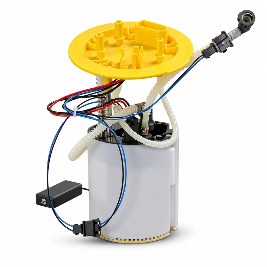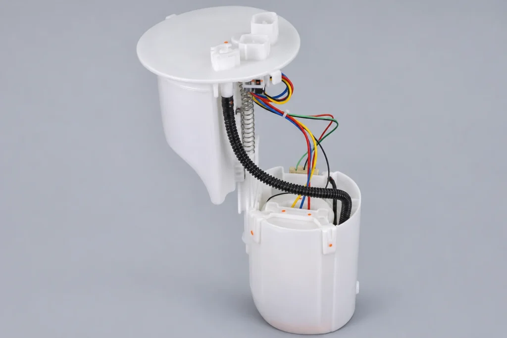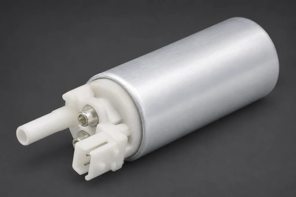
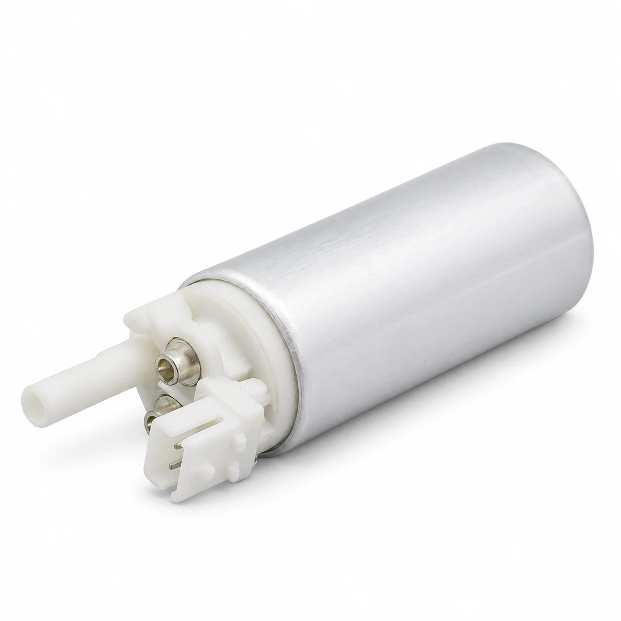
A PWM fuel pump system controls fuel delivery by varying a switching signal rather than simply running the pump whenever a relay closes. PWM means pulse-width modulation: the proportion of each cycle spent in an active state changes. However, the ECU command, controller output, and pump speed are separate quantities. A 50% reading does not automatically mean half pump speed, half pressure, or a failed supply circuit. Before selecting a replacement or interpreting a measurement, identify which signal you are observing and obtain the specifications for that exact vehicle, controller, and pump.
This guide concerns electrically controlled low-pressure supply pumps. It does not describe the metering valve on a diesel high-pressure pump as though it were the same component.
Where PWM appears in the fuel supply system
Start with the system architecture. An engine controller may send a low-current request to a separate fuel pump controller. That controller receives battery power and operates the motor through its power stage. On another design, communication may use a data network rather than a dedicated PWM command wire. A motor with integrated electronics introduces another boundary between external command and internal switching.
The name of a scan-tool parameter is therefore insufficient to identify its physical meaning. It might report requested delivery, a calculated command, feedback, or a duty measurement. Establish the parameter definition before comparing it with a trace captured at the pump connector. The two percentages may describe different circuits and legitimately differ.
Haltech’s fuel pump configuration documentation distinguishes switched operation from duty-cycle control and includes separate frequency settings. These are examples of configuration choices, not settings to copy into an unrelated production vehicle. For the wider supply layout, see our guide to return and returnless fuel systems.
Duty cycle and frequency describe different things
Frequency counts cycles per second, measured in hertz. Duty cycle describes a selected state’s duration divided by the complete period. Changing pulse width at a constant period changes duty cycle without changing frequency. Conversely, the same percentage can occur at different frequencies. A controller expecting one combination may not accept another.
Duty cycle (%) = active-state time ÷ complete period × 100. For an illustrative waveform with a 4 millisecond period and a 1 millisecond active interval, duty cycle is 25%, and frequency is 1 ÷ 0.004 seconds = 250 Hz. These numbers demonstrate arithmetic only. They are not recommended operating settings for any KANGSONG pump.
Positive duty measures time high; negative duty measures time low. In a simple low-side switched circuit, the controlled terminal may be close to ground while current is being enabled. Thus, a large positive-duty reading can correspond to a smaller energized interval. The correct interpretation depends on the circuit and measurement reference, not on the word “duty” alone.
The basic timing definitions are explained in Texas Instruments’ Real-Time Control Reference Guide. Establish polarity and the intended active state before using the formula. Do not apply a PWM percentage to a network message or a diagnostic feedback code without its documented meaning.
Why average voltage can be misleading
A digital multimeter may display an average or another processed value when connected to a switched circuit. Its reading depends on the meter function, bandwidth, waveform, and measurement points. A lower reading at an operating pump is not automatically equivalent to resistance in a continuously powered wire. The signal might be intentionally switched.
For an ideal rectangular waveform switching between zero and a fixed high level, the arithmetic average equals the high level multiplied by its high-state fraction. An ideal 14 V waveform at 40% high duty averages 5.6 V. That calculation describes the waveform; it does not establish motor terminal voltage during every part of switching, actual winding current, delivered flow, or serviceability.
Real motor circuits include inductance, switching paths, back electromotive force, and losses. A simple average cannot replace an oscilloscope capture where the manufacturer’s procedure calls for one. Likewise, a clean switching pattern does not prove that the pump supplies adequate fuel under load. Pressure and delivery evidence remain necessary.
Separate the command, output, and hydraulic response
| Observation point | What it can establish | What still needs verification |
|---|---|---|
| ECU request or scan-tool parameter | The reported operating request under the recorded conditions | Parameter definition, physical output, and controller response |
| Command wire at controller | Signal amplitude, timing, frequency, and polarity at that point | Acceptance by the controller and delivery of motor power |
| Controller supply and ground | Available electrical supply under the specified load | Power-stage operation and downstream circuit condition |
| Pump power circuit | Actual switched voltage and current when measured correctly | Pressure, flow, and compatibility with the intended operating range |
| Fuel pressure measurement | Hydraulic response at the documented test point | Sensor accuracy, test conditions, restrictions, and flow capacity |
This decision table organizes evidence rather than giving universal pass/fail thresholds. A practical example of the need to compare electrical command and response appears in Pico Technology’s Audi EC fuel pump case study. Its vehicle-specific observations should remain specific to that case.
Plan a useful measurement before connecting equipment
Obtain the correct wiring diagram, terminal identification, waveform expectations, and safe test procedure. Determine whether the scope inputs share a common reference. Incorrectly placing grounded test leads across switched points can create a short circuit. Use the instrument and vehicle manufacturers’ approved connection method, including suitable differential equipment where required.
Record battery condition, engine state, requested pressure if available, actual pressure, and the circumstances that reproduce the complaint. A capture during initial priming cannot be treated as proof of performance during acceleration. Preserve the original time base, vertical scale, probe ratio, current-clamp range, and signal reference with the saved waveform.
Choose enough capture time to see the event, then retain sufficient resolution to inspect switching. A display that compresses many pulses into a solid band may conceal brief interruptions. Do not interpret sampling artifacts as missing commands. Repeat a suspect measurement with a justified acquisition change before condemning hardware.
Pico’s duty-cycle measurement tutorial illustrates why high-state and low-state interpretation matters. Its example is a diesel metering valve, not a low-pressure electric pump; use the measurement principle without transferring its component behavior or settings.
What a replacement pump must match
Electrical compatibility extends beyond nominal system voltage. Confirm the approved control method, permissible switching conditions, starting behavior, current demand, thermal limits, and controller requirements using supplier data. A pump that runs when connected to a test supply has not thereby demonstrated compatibility with the vehicle’s controller throughout its operating range.
Motor technology also matters, but “PWM” does not uniquely identify it. Brushed motors and electronically commutated systems can involve pulse-width modulation in different ways. Our brushed versus brushless fuel pump comparison explains the technology boundary. Do not substitute one architecture solely because its connector appears similar.
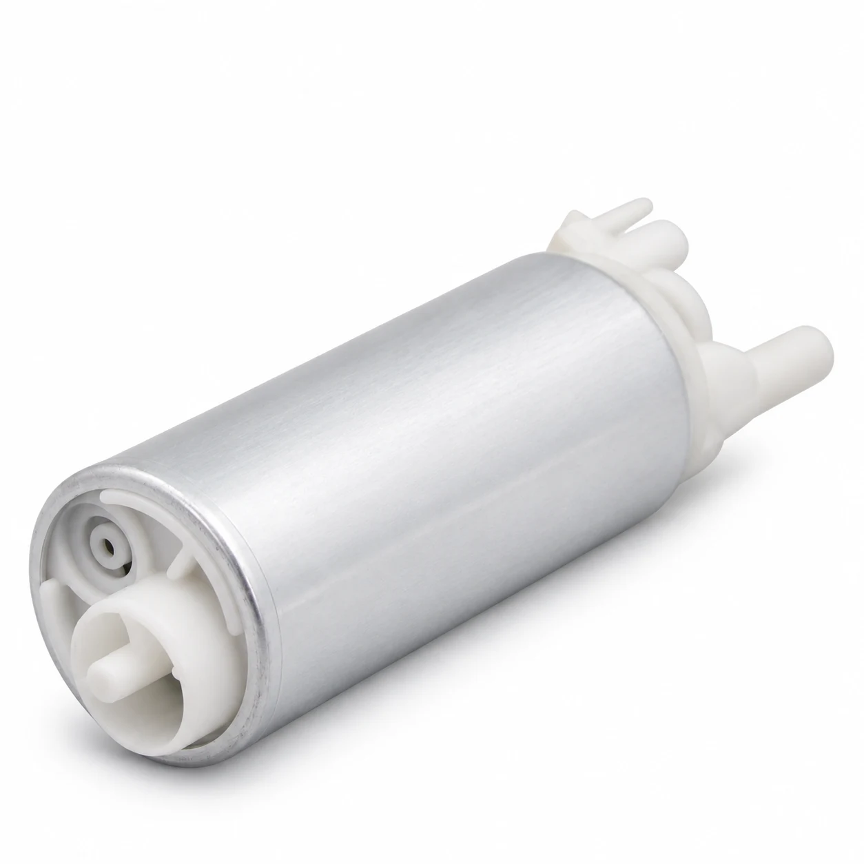
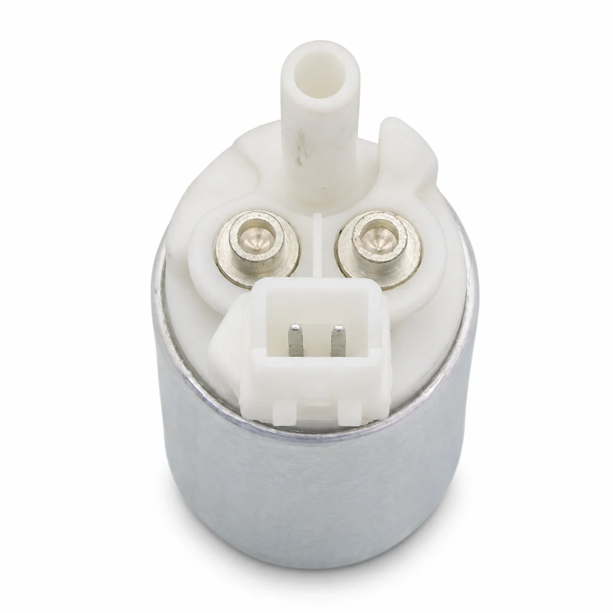
The website’s KS-360501 gasoline fuel pump product page provides a starting point for an application inquiry. The photograph used here does not establish its PWM operating limits. Request documented suitability for the exact control system before approving an interchange.
Build a supplier inquiry that prevents an expensive mismatch
Send the vehicle identification details, engine and fuel type, original pump and controller numbers, connector photographs, and the intended service conditions. Ask whether the proposed replacement is validated for the original controller or requires a different power stage. Treat any controller change as a system change requiring engineering review.
Request pressure-flow data at stated voltage, fuel, and temperature, together with current information and the relevant operating restrictions. Ask how the supplier identifies the tested sample and manages revisions. A single free-flow number without its conditions cannot resolve compatibility or prove that sufficient delivery remains at the required pressure.
For an intermittent problem, include time-aligned evidence rather than only a fault code. A request that rises while pressure falls is useful context, but it does not identify whether the root cause is the pump, electrical supply, controller, fuel availability, restriction, or pressure measurement. Keep these alternatives open until the corresponding checks are complete.
Where brushed-pump current detail is appropriate, use our separate current ramp testing guide. Switching frequency and motor rotation patterns are different phenomena, so do not count PWM edges as commutator events to calculate shaft speed.
Watch the switching principle
The Engineering Mindset’s tutorial below explains PWM using a small DC motor circuit. It is background education, not an automotive fuel pump controller design or permission to install a hobby circuit near fuel. Production fuel systems require their original safety strategy and qualified components.
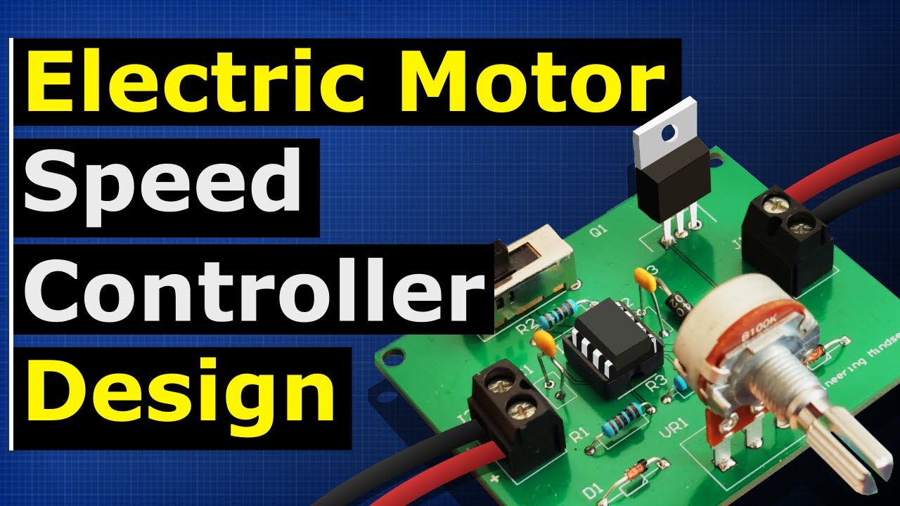
Watch the PWM motor control explanation on YouTube.
Frequently asked questions
Does 50% duty cycle mean half fuel pressure?
No. Duty cycle describes a signal’s timing. Pressure depends on the complete electrical and hydraulic system, its control strategy, and operating conditions. Use the vehicle’s specified pressure test instead of converting duty directly to pressure.
Can any 12 V fuel pump use PWM control?
Nominal voltage alone cannot establish suitability. Obtain written pump and controller compatibility information covering the intended control method and operating conditions before selecting a replacement.
Why do the scan tool and oscilloscope show different percentages?
They may represent different circuits, different parameter definitions, or opposite duty polarities. Identify the ECU request, controller output, measurement reference, and active state before comparing the readings.
Does a PWM waveform prove that the fuel pump works?
No. It establishes electrical activity only at the measured point. Confirm the supply, current response, pressure, and delivery under the documented conditions before deciding whether the pump and controller are serviceable.