A fuel tank suction jet pump uses a moving stream of fuel to draw additional fuel into another chamber or reservoir. It normally has no electric motor of its own, yet its operation depends on the motive flow supplied by the fuel system. A vehicle can therefore have fuel remaining in the tank while the electric pump’s pickup area runs short. Diagnosing that condition requires checking the tank’s actual transfer arrangement, hose connections, and fuel distribution rather than replacing the electric pump solely because the engine loses supply.
The electric pump and the jet pump do different jobs
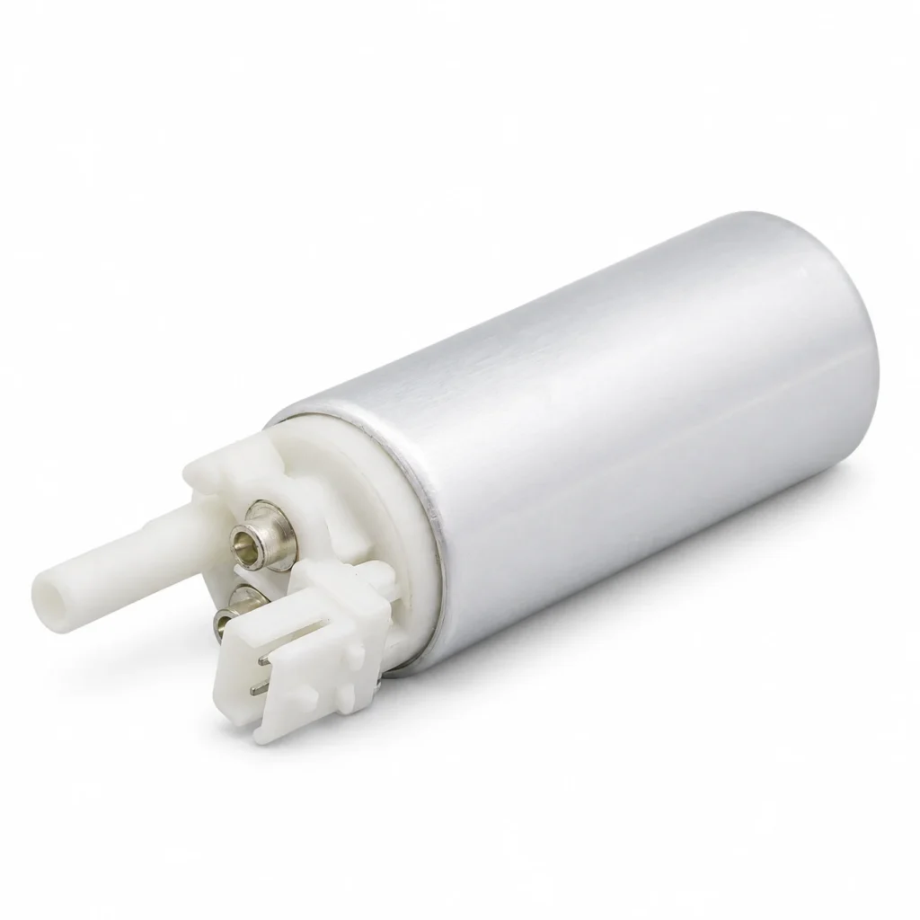
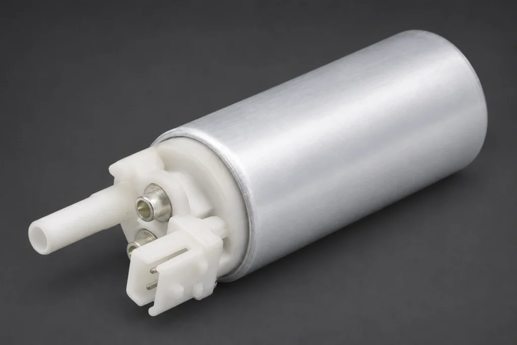
The electric fuel pump converts electrical energy into fuel flow and pressure. A jet pump uses part of an existing flow through a nozzle to entrain another stream. The mixed flow then travels into the intended chamber or reservoir. The jet pump is not an additional electric pump hidden behind a different name, and it cannot operate normally without its required motive flow.
Some systems use returning fuel as the driving stream; other arrangements supply the jet through another branch inside the module. The routing determines which pressure, restriction, or connection matters. A generic diagram can explain the principle but cannot identify the correct hose on an unfamiliar vehicle.
The reservoir is another distinct part. It helps keep fuel available near the electric pump inlet when fuel in the main tank moves around. A transfer arrangement may refill that reservoir, move fuel across a saddle tank, or perform another task. Identify the function in the manufacturer’s system diagram before choosing a test.
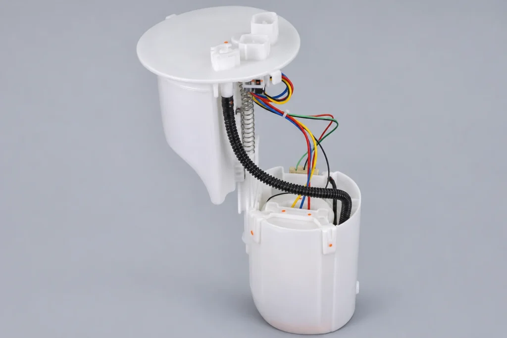
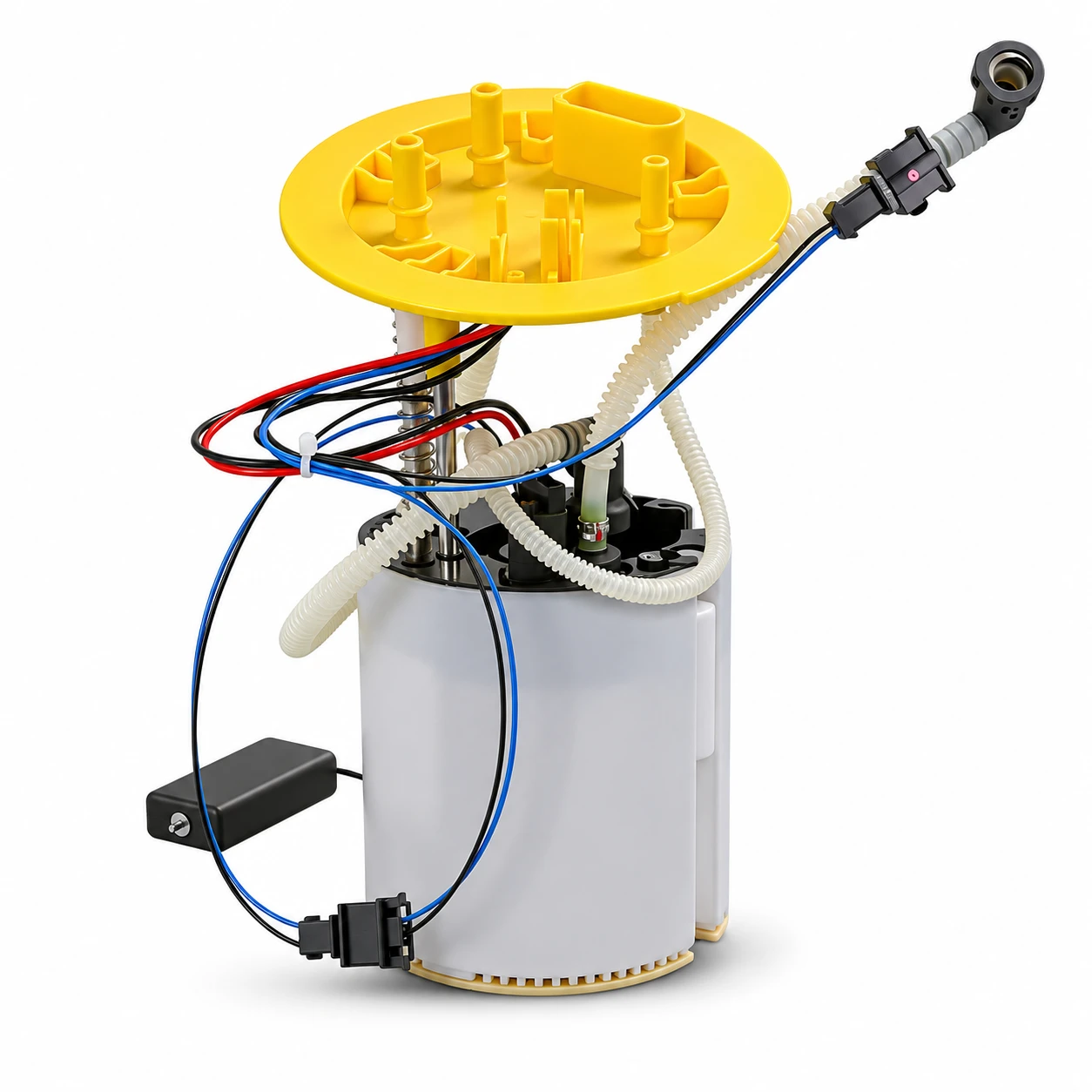
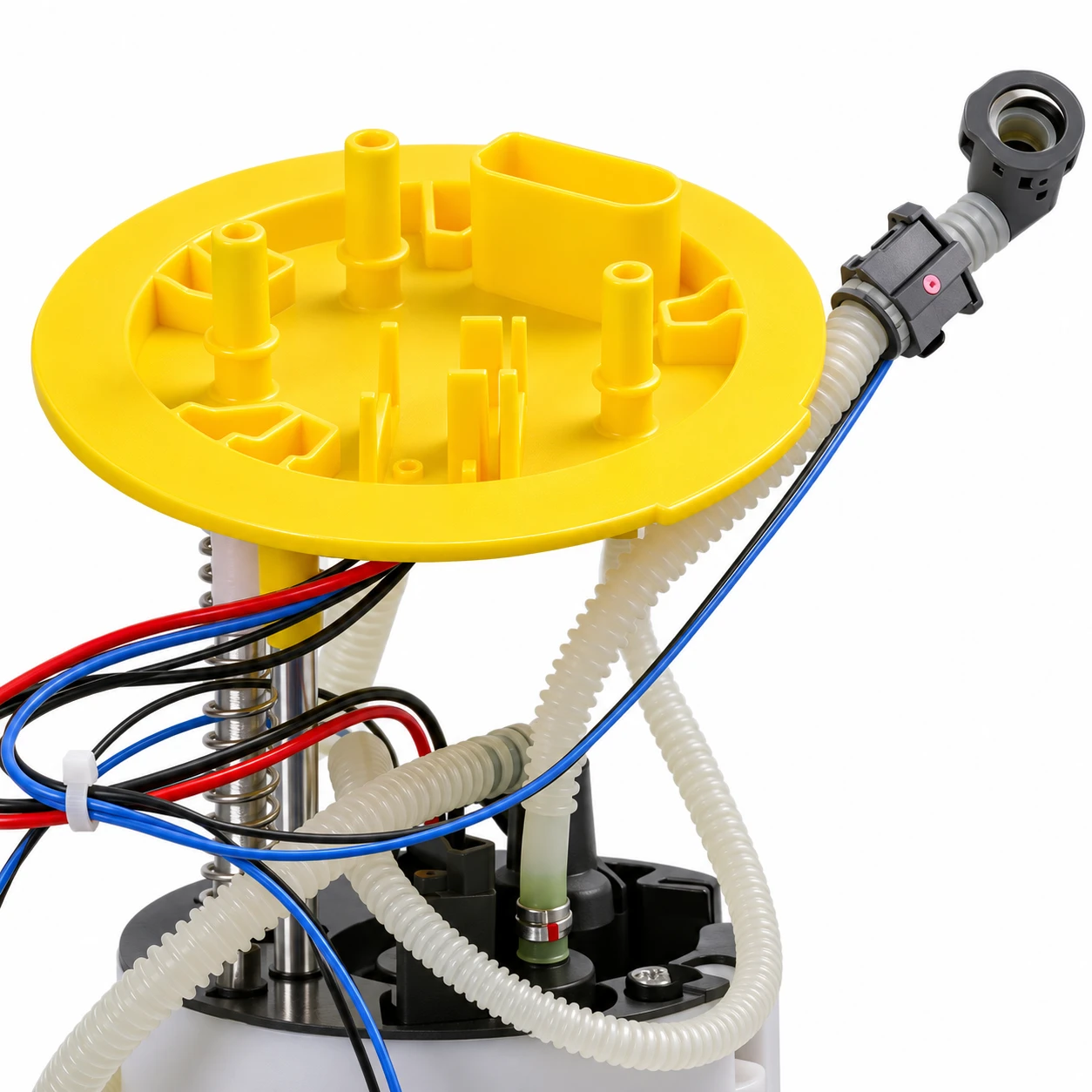
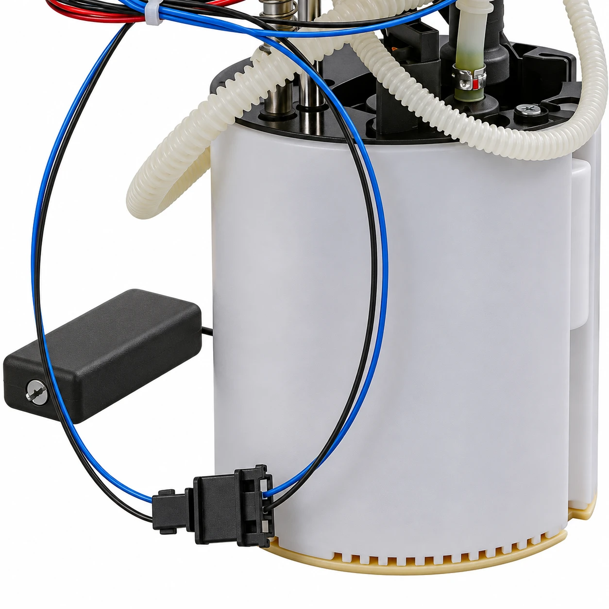
The website’s Audi A6C6 Quattro / KS-A613 module listing illustrates the complexity of a real in-tank assembly, including hoses, wiring, reservoir, and sender hardware. The product image is a physical reference, not a verified cutaway or proof of every internal hydraulic function. Confirm the tank and module revision before assigning a connector to a particular circuit.
Why tank shape changes the diagnosis
A saddle-shaped tank can hold fuel in separate low areas beneath a raised center. Once the level falls below that center, gravity alone may no longer move all the remaining fuel toward the main pickup. A transfer system is therefore needed in the relevant design. A single overall gauge reading may not show how that fuel is distributed.
The Audi A8 self-study program hosted by NHTSA includes an example tank layout with main and secondary level sensors and jet-pump connections. It demonstrates the need to trace the real plumbing. It does not establish that the pictured A6 product uses every detail of the A8 arrangement.
A reservoir-filling problem can produce a related but different complaint. Fuel may be available elsewhere in the tank while the immediate pickup area is not replenished correctly. Keep the vehicle’s approved diagnostic conditions in view; do not reproduce fuel-starvation events on public roads or deliberately operate the electric pump dry to prove a theory.
Start with the complaint pattern and the system diagram
Record the indicated fuel level, the actual fuel quantity if established safely, the conditions of the loss of supply, and whether the complaint followed tank or module work. A problem that appears after a replacement deserves a routing and compatibility review, not an automatic assumption that the new motor is defective.
Read available level-sensor data according to the vehicle’s diagnostic instructions. If separate chambers have separate sensors, their behavior may help identify unequal distribution. However, a sensor fault can also misrepresent the level. Confirm whether the readings are plausible before treating them as direct proof of trapped fuel.
Identify the electric pump, reservoir, motive-flow source, suction inlet, discharge route, check valves, and any regulator associated with transfer. Mark which connections are inside the tank and which are accessible externally. A clear flow map prevents a return, vent, or transfer line from being misidentified during inspection.
Distinguish supply failure, transfer failure, and gauge error
Low engine supply pressure can result from inadequate electric-pump output, electrical delivery problems, restricted plumbing, or lack of fuel at the pickup. The jet-pump investigation belongs within that broader diagnosis. Check the prescribed pressure and delivery tests and then determine whether the local fuel supply remains available under the relevant conditions.
A fuel gauge that still shows fuel is useful evidence but not a guarantee. The sender may be inaccurate, the tank may contain inaccessible fuel, or the interpretation of multiple sensors may be wrong. The site’s fuel-pump sending-unit guide addresses the measurement component separately from the transfer function discussed here.
The tank diagram must establish what each passive transfer device does. A jet may replenish a reservoir or transfer fuel between chambers, while vent-related components serve a different purpose. Do not assume that every connection near the reservoir is a cross-tank suction line. Trace the documented route and identify its source and destination before disconnecting anything.
Use observations to select the next check
| Observed condition | Relevant check | What the observation does not prove |
|---|---|---|
| Fuel remains indicated when engine supply falls | Confirm sender accuracy and fuel distribution using the approved procedure | That the jet pump is necessarily blocked |
| Complaint began after module replacement | Verify revision, hose routing, engagement, and transfer interfaces | That the new electric motor itself has failed |
| Transfer is weak while motive supply is below specification | Diagnose the supply source and its restrictions first | That replacing the passive jet will restore missing motive flow |
| Damaged internal connector or hose is found | Determine the approved repair scope and replacement parts | That an improvised hose or adhesive repair is acceptable |
| Liquid fuel appears in an inappropriate vent path | Stop operation and follow the vehicle-specific safety and campaign checks | That this is an ordinary sender calibration issue |
The table organizes diagnostic reasoning rather than prescribing a universal test. Actual pressure limits, fuel quantities, and permitted test arrangements must come from the service procedure. A qualitative match between symptoms and a table row is not a completed component diagnosis.
Inspect connections without creating a second problem
Tank work involves flammable fuel and vapor. Use trained personnel, approved draining and ventilation equipment, and the manufacturer’s isolation procedure. Do not use improvised open containers, unapproved electrical equipment, or a household vacuum around fuel vapor. Keep openings and disconnected lines protected from dirt and moisture.
Internal connectors can be delicate. The Volkswagen suction-jet-pump recall repair instructions hosted by NHTSA warn that improper connector handling can cause damage and repeat repair. Those instructions apply to the campaign vehicles; they are evidence of the importance of correct handling, not a universal removal sequence.
Before releasing a connection, identify its locking mechanism and required tool. Inspect engagement after installation using the specified check. A connector that appears seated in a photograph may not be latched, and pulling on a fragile line can introduce damage that was not present before inspection.
Document any hose kink, split, displacement, or damaged interface. Do not enlarge a jet nozzle, add an unverified restriction, or modify a tank to make a replacement fit. The transfer function depends on the designed flow path. A change that seems harmless at idle can alter delivery under another condition.
Verify module compatibility beyond the electric motor
A replacement assembly must satisfy more than voltage and connector fit. Check the flange, reservoir geometry, installed height, sender arrangement, line locations, and transfer connections. The pump motor may be suitable while the surrounding module differs in a way that affects fuel distribution. This is why a bare motor and a complete module are different purchasing decisions.
Compare the removed assembly with the approved replacement using the original part number and documented supersessions. Ask whether transfer hoses, seals, regulator components, and sender parts are supplied or reused. Preserve the exact supply scope in the order rather than assuming everything shown in a catalog image is included.
For background on these purchasing boundaries, see fuel pump assembly versus bare pump. The return versus returnless system guide explains another related distinction. Neither broad category alone proves that a specific module supports the required transfer arrangement.
Confirm the result before returning the vehicle
After the authorized repair, perform the specified leak, pressure, and level-system checks. Verify that the original complaint is resolved under approved conditions and that no internal hose or sender movement is obstructed. Keep the before-and-after observations together so the repair record shows what changed and what was actually measured.
For a supplier inquiry, provide the VIN, tank type, original module and jet-pump identifiers where available, connector photographs, and the diagnosed fault. If the failed part is internal to the tank or unavailable separately, clarify the approved replacement assembly. The lowest-priced component is not a complete solution when the required mating interface remains damaged.
Further learning: how a jet creates suction
MatthiasWandel: The Venturi effect
This neutral physics demonstration by Matthias Wandel explains the Venturi effect and suction. It supports the fluid-mechanics principle only. Its demonstration equipment is not suitable as a design or test rig for gasoline, and the video does not supply vehicle transfer-flow specifications.
FAQ
Does a suction jet pump have its own electric motor?
The passive jet-pump arrangement discussed here uses an existing motive stream. The vehicle may contain other electrically driven transfer devices, so confirm the actual system diagram.
Can the engine run short of fuel while the gauge still shows fuel?
Yes, if fuel is not available at the pickup despite remaining elsewhere, or if the indicated level is inaccurate. The cause must be established through the approved checks.
Will a stronger electric pump automatically fix poor transfer?
No. Damaged routing, incorrect interfaces, restrictions, or a different transfer design can remain. Verify the complete module and tank arrangement instead of assuming more pump capacity solves it.
Can every jet-pump fault be repaired with a separate jet replacement?
No. Service scope varies. Some conditions require another assembly or associated parts, particularly when internal connectors or tank interfaces are damaged.