VVT solenoid symptoms can include rough idle, reduced response, and camshaft timing faults, but those symptoms do not prove that the solenoid needs replacement. The oil supply, wiring, control signal, camshaft position feedback, and mechanical timing can produce overlapping complaints. A useful diagnosis checks those conditions in sequence and compares commanded camshaft position with the actual response. For a repair shop or parts buyer, the goal is to identify the failed part and its exact location before ordering an oil control valve.
What the solenoid actually controls
In a hydraulically operated cam-phasing system, the oil control valve meters or directs engine oil to the actuator that changes camshaft timing. The solenoid is the electrically operated part of that control arrangement. The actuator or phaser is a different component, and the camshaft position sensor supplies feedback rather than directing oil. Similar terminology on a parts ticket can easily blur these roles.
Manufacturer documentation describes the control arrangement for each engine family. Real engines use different implementations, so the diagnostic procedure must match the engine’s actual hydraulic and electrical arrangement. An explanation of one system is not a test specification for every valve sold under the VVT name.
Some systems vary camshaft phase, others change valve lift, and some combine functions. Confirm what the vehicle has before connecting a fault description to a product. A valve listed for a particular camshaft or engine cannot be selected merely because another engine uses the same broad technology.
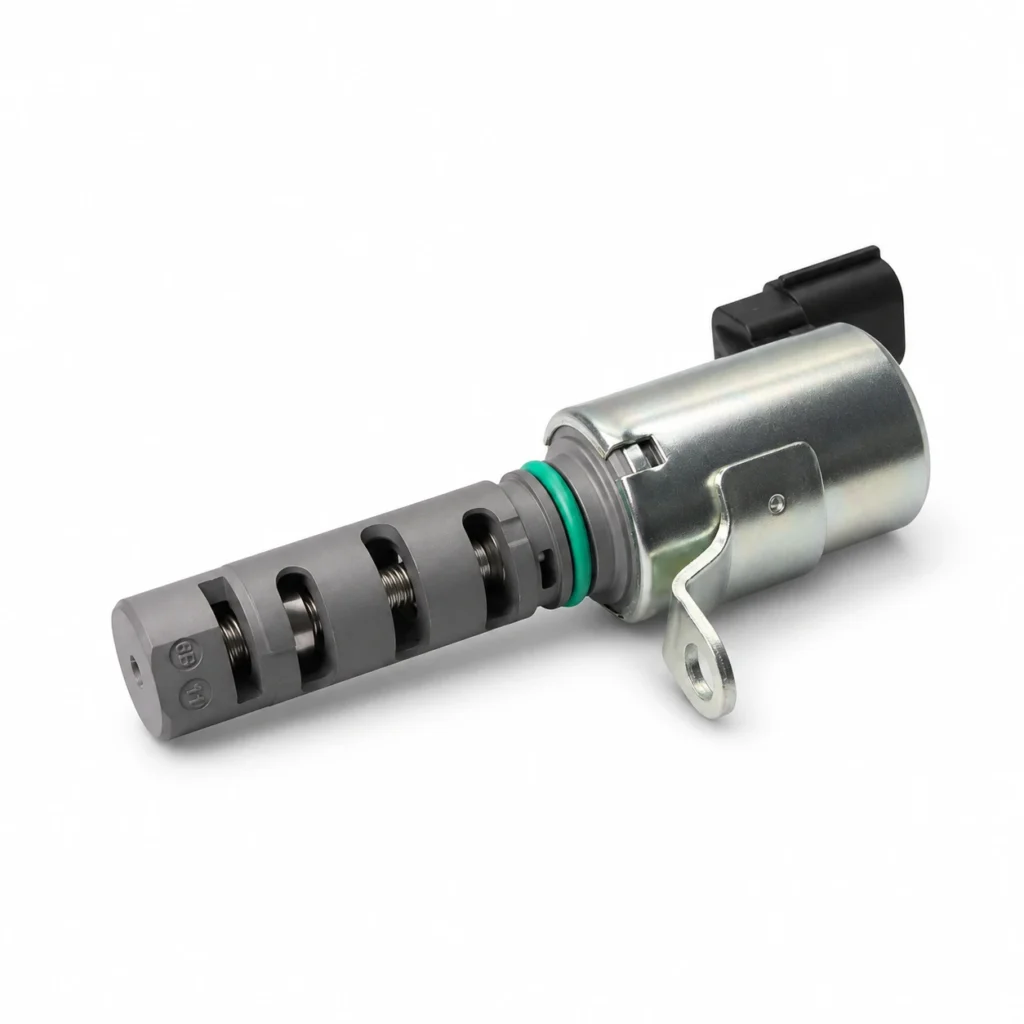
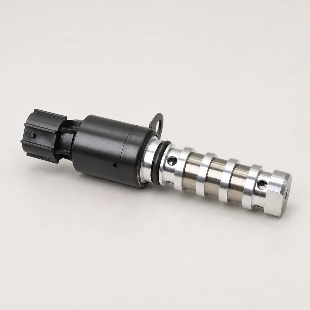
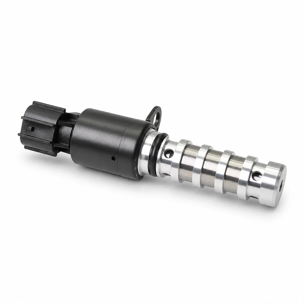
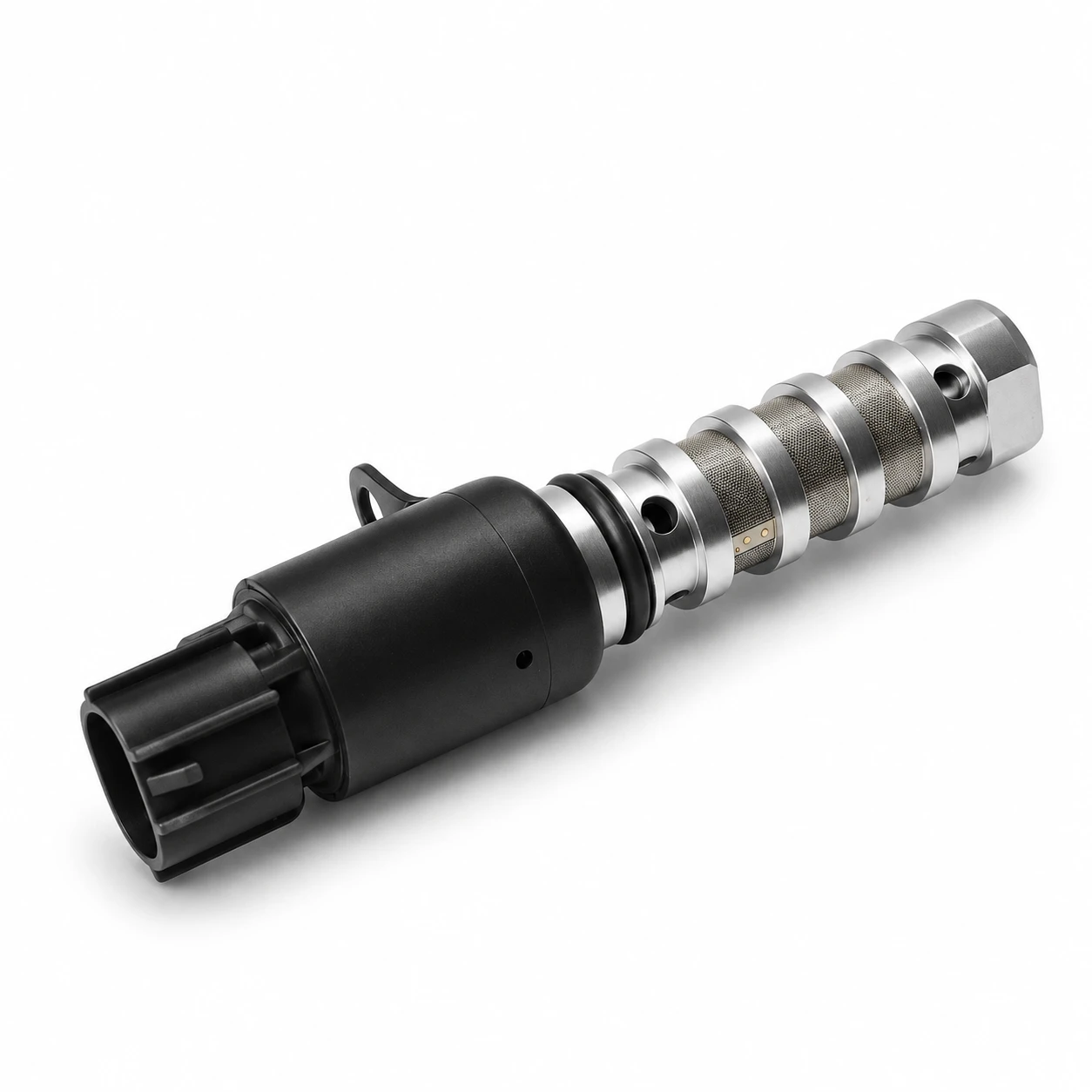
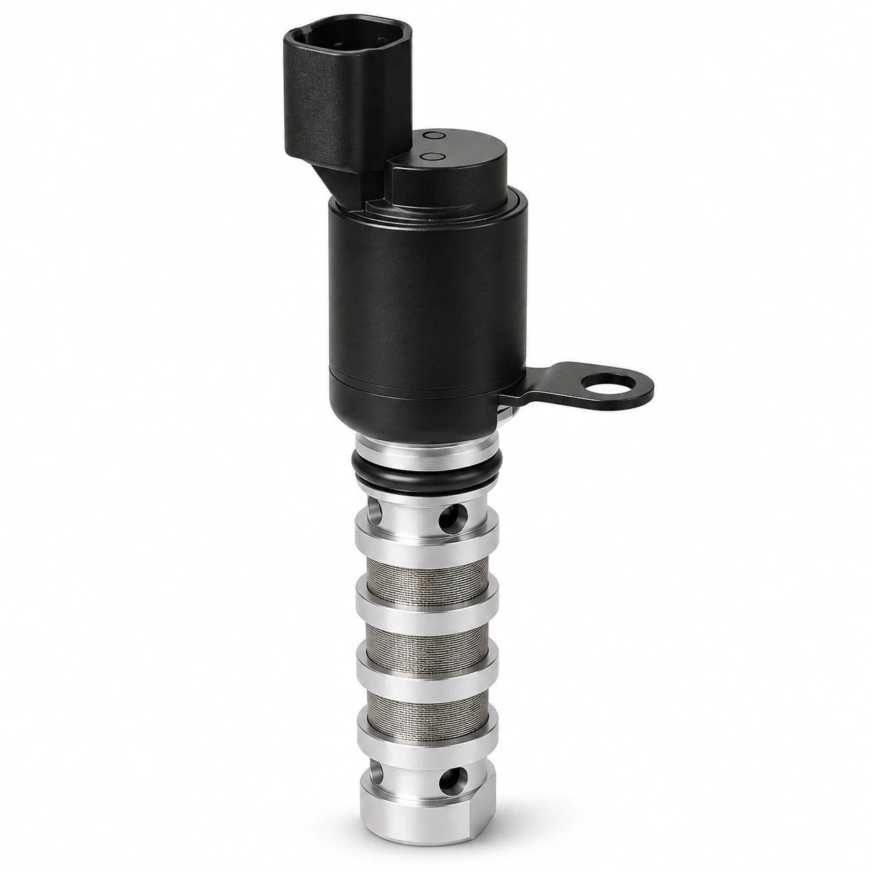
The website’s 24355-2G500 / KS-VVT105A valve listing supplies a real reference for the pictured component. Use the part number, body configuration, connector, and application documentation together. The photograph does not establish resistance limits, command frequency, or the correct test voltage.
Recognize symptoms without turning them into a verdict
An unstable idle can be consistent with incorrect camshaft position, but ignition, fueling, air leaks, compression, and other faults can also affect idle. Record when the problem appears: cold start, hot idle, acceleration, or a particular load transition. That pattern helps choose the next test and prevents a generic symptom list from becoming a replacement recommendation.
A camshaft timing code is also a starting point. Read the full manufacturer description, including bank and camshaft identity. A circuit fault, slow-response fault, position-performance fault, and crank-to-cam correlation fault do not all ask the technician to perform the same check. Preserve freeze-frame data before clearing the memory.
Noise needs similar care. A start-up rattle may involve a phaser, timing drive, or another mechanical source. A buzzing or clicking valve can show that something is being energized, but sound alone does not demonstrate correct hydraulic flow or camshaft movement. Avoid ordering both a phaser and a solenoid simply because they share a diagnostic label.
Check engine oil before interpreting valve response
Establish the oil level, the specified oil grade, service history, and any warning conditions. Inspect the oil as directed and check pressure when the diagnostic procedure requires it. A hydraulic actuator cannot respond normally without an adequate supply. Changing an electrical component cannot restore missing pressure or clear an upstream restriction by itself.
Correct oil viscosity matters under the operating temperatures in which the system is expected to work. However, do not assign a universal minimum pressure or blame every delayed response on viscosity. The permitted pressure and test conditions come from the engine’s service information. Record temperature and engine speed alongside a pressure reading so the number can be interpreted.
The Subaru AVCS diagnostic bulletin hosted by NHTSA illustrates a structured investigation covering oil, electrical connections, passages, and mechanical conditions. Its individual resistance values and procedures apply to its stated vehicles. The broader lesson is to follow the complete diagnostic path rather than stop at the first named valve.
Separate electrical control from hydraulic movement
Inspect the connector and harness for damage, poor engagement, oil intrusion where relevant, and damaged terminals. Identify the correct circuit from the wiring diagram. A connector that fits the valve does not establish the correct pin assignment, and a voltage reading taken without the specified load may not reveal an intermittent connection problem.
Measure coil resistance only using the procedure and temperature conditions specified for the part. A value inside the permitted range can rule out some winding defects, but it does not demonstrate that a spool moves freely or that oil reaches the phaser. Similarly, a circuit fault can originate in wiring or control hardware rather than the valve itself.
Use a compatible scan tool’s approved actuator test where provided. Observe the commanded state and the engine’s response while respecting the test conditions. Avoid applying continuous battery power to an unidentified valve. A pulsed control device may require limits that a direct-power test does not respect.
Compare command, feedback, and operating conditions
Commanded camshaft angle expresses what the controller is requesting. Actual camshaft angle is the reported response. A persistent difference can justify further diagnosis, but it does not by itself isolate the control valve. Check whether the operating conditions allow the test, whether the feedback is trustworthy, and whether another fault has disabled normal control.
Where the procedure permits comparison between banks or camshafts, keep the conditions consistent. One bank’s response may help identify an abnormal pattern, but different camshafts can have different targets and limits. Do not expect identical angles simply because two graphs are displayed on the same scan-tool screen.
Use this table to keep the observation separate from the conclusion. It is a qualitative diagnostic organizer based on the system roles and manufacturer diagnostic approach described above; it supplies no substitute specifications.
| Observation | What still needs checking | Premature conclusion to avoid |
|---|---|---|
| Circuit fault with no normal valve command | Connector, wiring, power or control path, and coil under the specified test | The phaser must be mechanically damaged |
| Command changes but reported angle responds poorly | Oil pressure, valve operation, passages, feedback, and phaser condition | The solenoid is the only possible cause |
| Symptoms change substantially with oil temperature | Specified oil, pressure at the relevant temperature, and approved response tests | A different oil grade will necessarily repair the problem |
| New valve produces the same fault | Correct part and position, original diagnosis, supply and mechanical condition | A second new valve should be fitted immediately |
| Correlation fault or mechanical noise accompanies the complaint | Manufacturer timing and mechanical inspection path | Clearing the code establishes a completed repair |
Inspect contamination and mechanical conditions when directed
If the service procedure calls for valve removal, protect the opening and preserve contamination evidence. Inspect screens, seals, and visible ports without forcing tools into precision surfaces. Record damage or debris before cleaning. Do not assume that a solvent soak is approved for every electrical coil, plastic component, or sealing material.
The valve may be only one affected part. Contamination can originate elsewhere, while a damaged screen can create another problem. The repair plan should address the source and the required inspection area. Removing visible debris from a valve is not proof that all oil passages or the actuator are clear.
A GM service update for camshaft actuator bolt binding is another example of a specific mechanical condition requiring a specific repair. It should not be generalized to unrelated engines. It demonstrates why the current bulletin and application identification matter when symptoms appear to point to a familiar component.
Order the correct valve and verify the repair
Provide the supplier with the VIN, engine code, production date, original part number, bank, and intake or exhaust position as defined in the manual. Add photographs of the connector and mounting arrangement. Ask for written confirmation of the cross-reference and any supersession, rather than accepting a match based only on overall body shape.
Check seal location, installed depth, mounting tab, and port geometry against the approved part. Do not infer internal interchangeability from an identical connector. The site’s OEM and ODM services page describes the business service scope; a particular replacement still requires application-level evidence.
After the authorized repair, perform the specified checks, any required learning procedure, and the relevant drive cycle. Compare the result with the saved complaint conditions. The intake versus exhaust VVT valve guide covers position identification. For a different cam-driven component, the high-pressure pump follower guide explains a separate inspection boundary; its pump-drive checks must not be treated as VVT valve tests.
Further learning: phase and lift are different
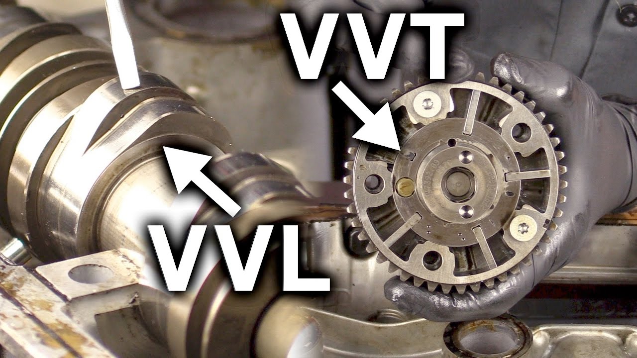
Engineering Explained: Variable Valve Lift vs Variable Valve Timing – VVL vs VVT
Engineering Explained’s lesson distinguishes variable valve timing from variable valve lift. That distinction helps identify the system being diagnosed. The lesson explains principles and does not provide resistance limits or a removal procedure for the pictured oil control valve.
FAQ
Does a camshaft timing code mean the VVT solenoid is bad?
No. The code identifies a monitored condition. Oil supply, wiring, feedback, mechanical timing, and actuator behavior may need checking before the failed component is known.
Can the coil pass a resistance test while the system still fails?
Yes. Resistance testing addresses only part of the electrical condition. It does not establish free valve movement, adequate oil flow, or correct phaser response.
Is cleaning always a suitable alternative to replacement?
No. Cleaning must be permitted for the part and condition. A damaged valve, contaminated circuit, or unapproved cleaning method requires a different repair decision.
What proves the repair worked?
The required post-repair checks and operating evaluation must resolve the original complaint. A cleared code or a quiet idle alone is not sufficient evidence for every failure.