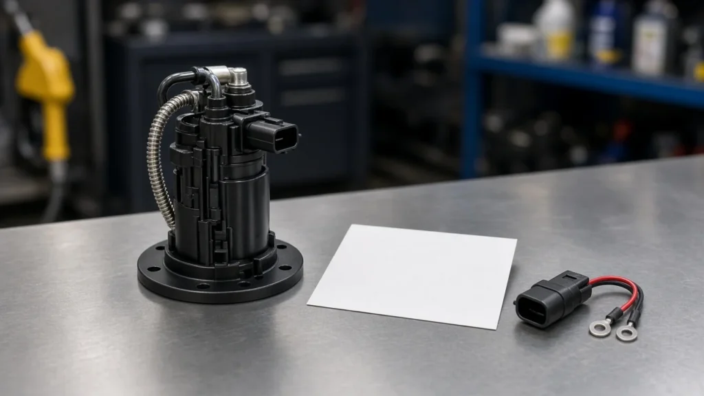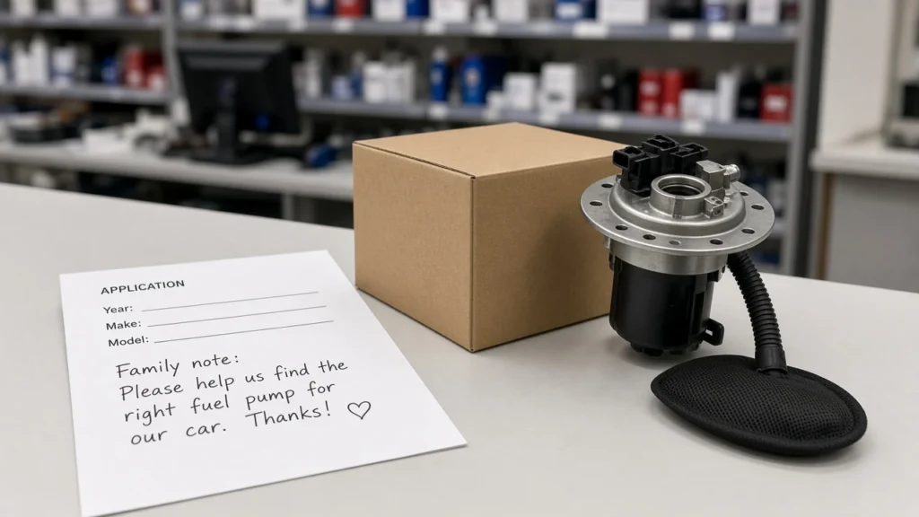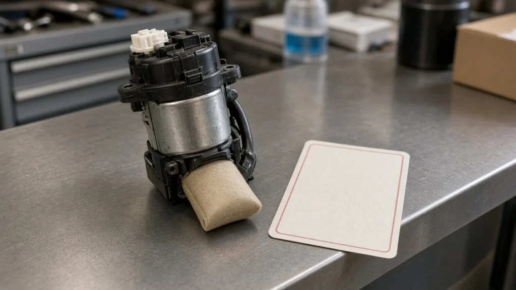
Read a fuel pump control module wiring diagram by giving power, ground, pump output, and the control line to the frame-mounted driver. The plug on the in-tank fuel pump only carries the feed that has already left that driver. A 2007 sheet and a 2008 sheet are separate drawings, and the pump kit later in this page is for older C/K trucks.
Counters get this search after a pump has already been changed and the truck still will not prime. The useful move is to name the connector on the frame before anyone talks about the wires at the tank.
Start at the frame-mounted driver, not the tank plug
The sheet is drawn around the fuel pump control module on the frame, also called a fuel pump driver module. Tank-sender wires are the far end of one circuit, so they cannot stand in for the whole connector.
On late-2000s gasoline trucks the box sits out of the tank, where road spray reaches the case and the harness. A counter who photographs only the pump flange will miss the command wire, the module supply, and the ground that never enters the tank.
From the field: On a 2007 Silverado thread, the owner had already replaced the pump, and a reply described a fuel pump driver module bolted to the frame above the spare tire, with corrosion along the case seam (GBodyForum, 07 Silverado fuel pump power).
That reply also said a replacement box still had to be programmed at a dealer. Treat the sentence as what that thread reported for one 4.8 truck, and pair it with the year sheet rather than with a catalog guess.
Sort power, ground, pump output, and the control line
Power, ground, pump output, and the control line are four different jobs on the driver connector. A Ford 4.6L and 5.4L test page for 2004-2010 F-Series trucks uses the same split: supply in, chassis ground, a command from the powertrain controller, and separate wires onward to the pump.
Use the function column on the sheet in front of you. Ignore any urge to borrow a color from a different year, a different engine, or a Ford pin list.
| Role on the driver | What the function column is doing | Where that wire stops |
|---|---|---|
| power feed | Brings battery or run/crank supply into the driver | Ends at the driver, not at the pump pins |
| chassis ground | Ties the driver to a ground path | Ends at the driver or a named ground point |
| pump output | Leaves the driver toward the pump | Continues to the in-tank plug |
| control line | Carries the command from the engine controller | Ends at the driver |
A power feed can be a battery line or a run/crank line. Both are supplies into the box. Neither one is the wire the pump motor uses as its own feed.
Chassis ground and a sensor low reference can share a ground idea and still be different rows on the sheet. Read the function name on that row. A shield or a low reference is not automatically the pump’s return.
After the ground row, follow the circuit that leaves toward the tank. On some drivers the pump side is a steady feed plus a pulsed return.
Call that pulsed return pump output as well. It is separate from the chassis ground you just identified, and it is separate from the command coming from the controller.
The engine controller’s command lands on the control line. On the Ford pages it is called fuel pump control, and a monitor wire may run back the other way.
Treat a monitor as a report to the controller. It does not replace the command, and it does not power the pump.
Leave the in-tank pump wires on the pump plug
The in-tank fuel pump plug carries only the feed the driver sends it. Two pins, or sometimes three with a level sender, are the end of the pump output. They do not include the control line.
Older gasoline pumps, including the 2-pin C/K kit later on this page, are built as motors with a supply and a return. The engine controller never lands on those pins. The controller lands on the driver, and the driver decides what the pump sees.
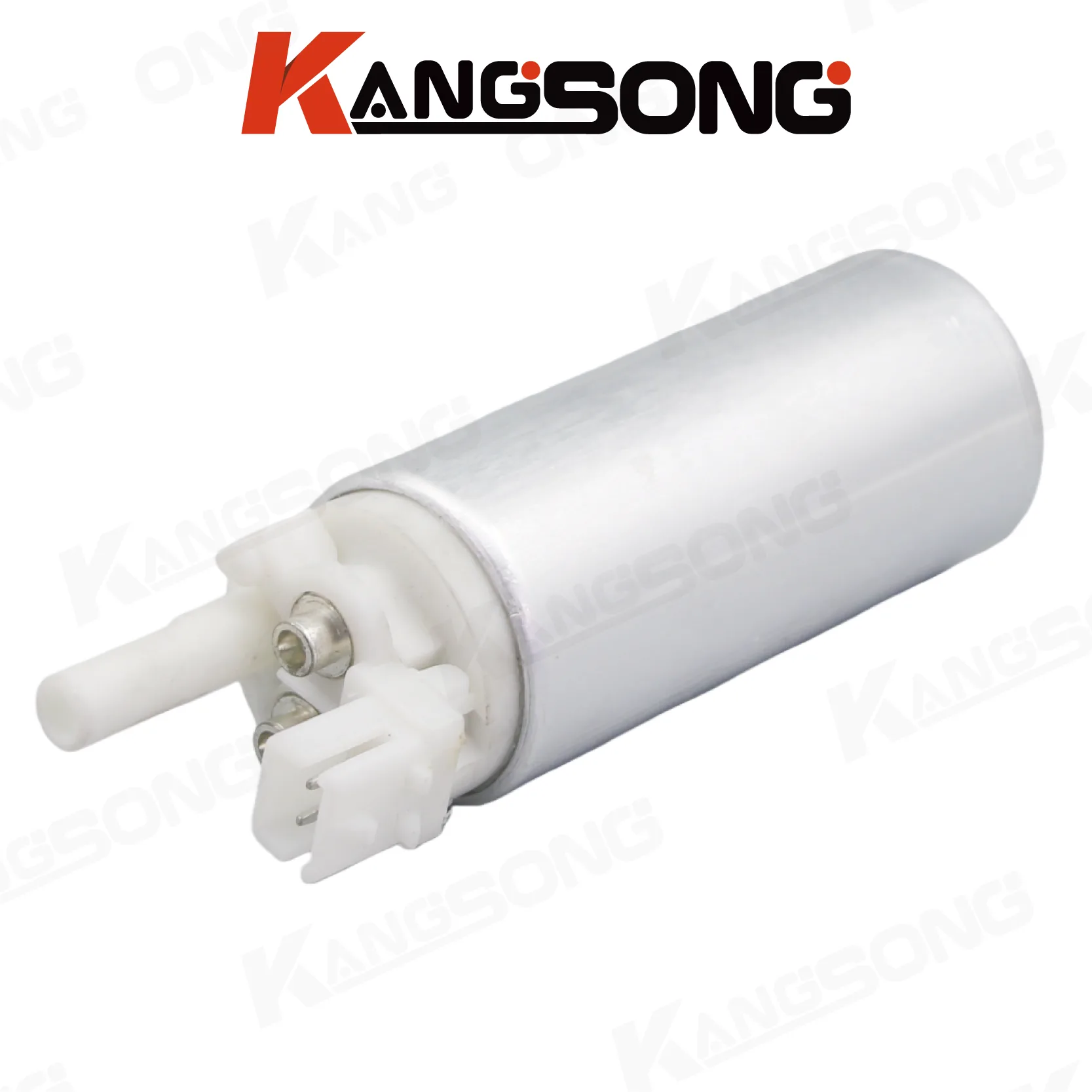
A counter who labels the pump’s two wires as “module power” and “module command” will order the wrong service. Module power and the command stay on the frame connector. The pump wires are downstream.
If the diagram shows a sender or a pressure sensor on the same tank unit, keep those signals in their own rows. A level signal is not pump output, and a 5-volt reference for a sensor is not the control line.
Treat a 2007 Chevy Silverado search as its own sheet
Open a 2007 chevy silverado fuel pump control module wiring diagram as the 2007 Silverado sheet for that cab and engine. The page that ranked for a 2007 Cab and Chassis Silverado 3500 path warned that it described other vehicles, including 2008 SUVs, so the color column on that page stays off this article.
Look for a title such as Fuel Pump Flow Control Module (except LY6), then read the warning before the table. When the warning and the URL disagree, stop and open the sheet that matches the truck in the bay. Cavity counts on that warned page also disagreed with the connector description, which is another reason to leave the grid unpublished here.
A 2007 underhood fuse chart prints a fuel-pump fuse for the pump and sender, and a separate fuse named for the fuel system control module. The FSCM label on that chart is for gas engines except L96 or LU3. Two fuse names mean the module supply and the pump supply are tracked as different loads.
The same 2007 thread that placed the box above the spare tire was a 4.8. A 6.0 sheet with an “except LY6” title is not that 4.8 truck. Ask which engine is in the VIN before you treat any 2007 grid as shared property.
Treat a 2008 Chevy Silverado search as its own sheet
Open a 2008 chevy silverado fuel pump control module wiring diagram as the 2008 Silverado sheet, and keep it apart from the 2007 file. The page that ranked under a 2008 Silverado 1500 5.3 path warned that it was about 2007 Sierra and Silverado trucks.
That warning is the whole lesson. A URL with 2008 in it can still be serving a 2007 drawing.
Function names on the warned page included ground, battery positive, a relay control, and a fuel-pump supply. Those names support the four-role sort. They do not authorize a color list, because the page said it was a different vehicle.
Sheet titles in the 2008 index also split fuel-pump controls by engine family, including pages marked around LMG, LY6, and LC9. A 5.3 truck and a 6.0 truck can sit on different figures even in the same model year. Ask for the RPO or the engine size before anyone merges the files.
A later NHTSA-hosted GM sheet, PIT5636D, covers 2019 and 2020 Silverado and Sierra trucks and treats the fuel pump driver control module as its own service part, split by engine family. That sheet is not a 2008 pinout. It does show why a driver and a pump stay on different lines of an order, even years after these trucks.
On listed Jaguar Land Rover models, NHTSA-hosted message SSM76149 says replacing the driver module does not close a harness or connector fault. The Chevrolet sheets above are a different brand. The shared point is only that the wires and the box are different work.
Hand the counter the truck year before you name a pump
Year, engine, and “driver or pump” have to be on the note before a part number is. A 2007 Silverado sheet and a 2008 Silverado sheet can both mention a fuel pump control module and still be the wrong drawing for the truck outside.
| Search the buyer typed | What to open | What to leave off the quote |
|---|---|---|
| 2007 Chevy Silverado fuel pump control module wiring diagram | The 2007 Silverado sheet whose warning matches that truck, plus the fuse names | Colors, cavity counts, and any 2008 grid |
| 2008 Chevy Silverado fuel pump control module wiring diagram | The 2008 Silverado sheet after the cross-vehicle warning is read | Colors, cavity counts, and any 2007 grid |
| 1987-1995 C/K pump | The printed pump kit, KS-360501 | Any Silverado driver |
Write down whether the customer measured supply at the frame box, at the pump plug, or only at a fuse. The 2007 chart’s split between the pump fuse and the FSCM fuse is there so those two readings are not called the same circuit.
Cluster pages on this site already cover the neighboring jobs. Use them as the next page, and stay on this page for line ownership.
- Fuel pump control module failure is the page for driver-versus-pump diagnosis.
- Fuel pump driver module connector is the page for connector evidence before an order.
- P025A fuel pump module control circuit open is the page for that code.
- Fuel pump assembly vs fuel pump is the page for hanger-versus-pump wording.
- Relay-fed pump wiring is the page for a simple relay feed.
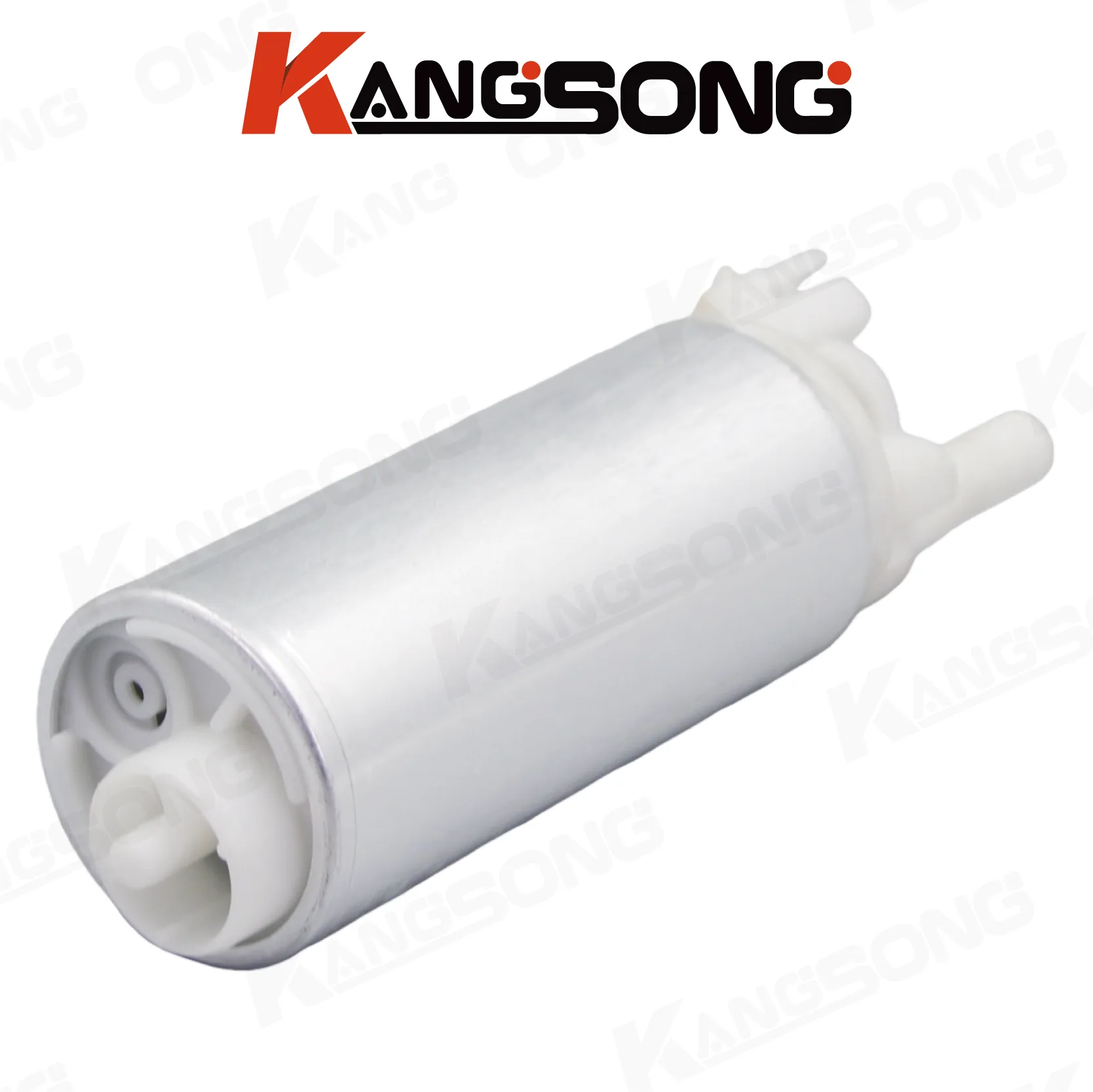
Choose the C/K kit as the pump, not the module and not a 2007-2008 Silverado part
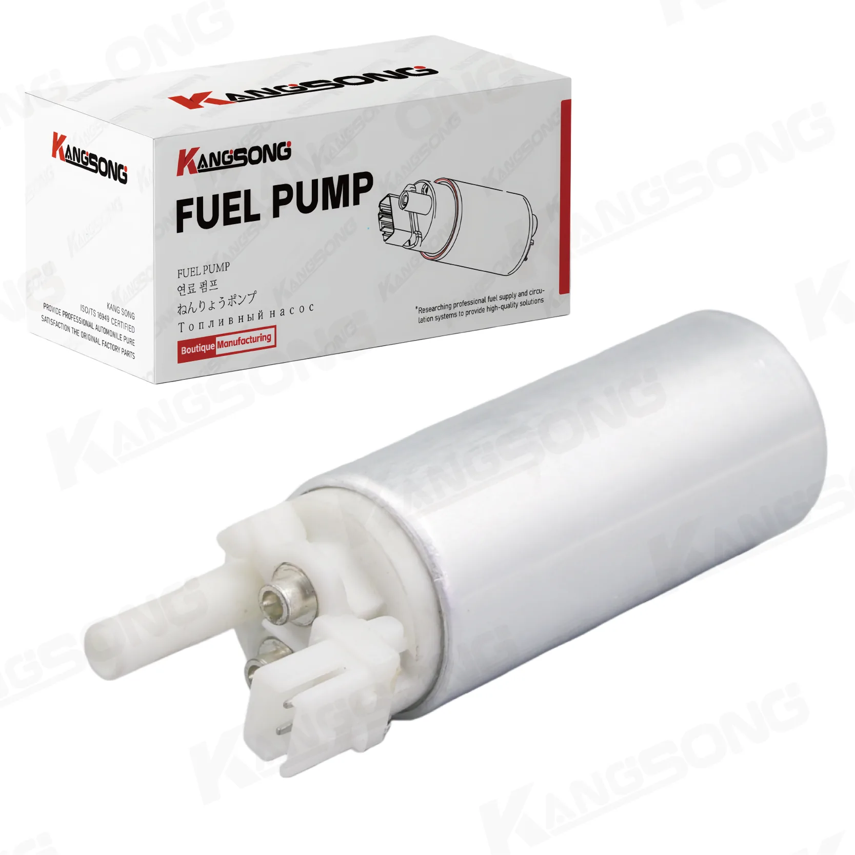
The kit is the pump, not the module, and it is not a 2007-2008 Silverado part. Kangsong does not publish a fuel pump control module SKU, so a Silverado driver request cannot be filled from this catalog line.
The Kangsong electric gasoline fuel pump with installation kit, part KS-360501, is a DC 12V pump printed for 1987-1995 C/K 1500, 2500, and 3500 trucks, with a 2-pin connector, a flow band of 43.3-49.5 Gph, and OE cross numbers 25168719 and E3902.
Those printed figures describe the motor in the tank on the trucks in the title. They do not describe a frame driver, a 2007 fuse, or a 2008 connector. A 2-pin pump plug matches the “leave the command on the driver” rule: this kit has no pin for an engine-controller command.
Open the electric gasoline fuel pump with installation kit when the job is that 1987-1995 C/K pump. For a different pump, use the Kangsong pump catalog.
FAQ
Is the fuel pump control module the same part as the in-tank pump?
The module is the frame driver that receives the control line. The in-tank fuel pump is the motor at the end of the pump output. KS-360501 is the second of those, and only for the printed C/K years.
Why do a 2007 search and a 2008 search open different sheets?
Because the pages that opened carried different warnings and different title years. One 2007 path warned that the drawing described other vehicles.
One 2008 path warned that the drawing was about 2007 trucks. Keep each file with the truck it actually describes.
Where did one 2007 Silverado owner find the driver box?
On the frame, above the spare tire, in the GBodyForum thread about a 2007 4.8. The same posts described corrosion at the case seams. That is one truck’s location report, not a measurement for every cab.
What does a separate FSCM fuse tell a counter?
The 2007 chart gives the fuel pump one fuse name and the fuel system control module another, with the module fuse limited to gas engines except L96 or LU3. Supply for the box and supply for the pump are labeled as different loads.
Can the pump’s two pins stand in for the engine controller’s command line?
The two pins are the end of the pump output. The control line arrives at the driver from the engine controller and stops there. A 2-pin C/K pump has nowhere to land that command.
Why does a later NHTSA-hosted sheet give the driver module its own part number?
PIT5636D, for 2019 and 2020 Silverado and Sierra trucks, treats a software fault in the fuel pump driver control module as a module replacement, with the service part split by engine family. It is not a wiring grid for 2007 or 2008, and the part numbers on it are not quoted here.
What should a buyer send when the request says wiring diagram but the truck is a 1987-1995 C/K?
Send the year range and the OE cross, 25168719 or E3902, and order the pump kit. That request is not a 2007 or 2008 driver, and it is not filled by inventing a control-module number.
References
- Fuel pump driver module tests for 2004-2010 Ford 4.6L and 5.4L trucks
- NHTSA-hosted GM preliminary information PIT5636D
- GBodyForum thread on a 2007 Silverado fuel pump that still would not run
- NHTSA-hosted JLR message SSM76149 on driver-module replacement
- 2007 Chevrolet Silverado fuse chart with separate pump and FSCM labels