Fuel injector dead time is the compensation an ECU uses for the difference between an electrical command and the injector’s effective fuel delivery. It changes with operating conditions, especially supply voltage, and it must match the injector and the ECU’s definition of the data. A flow-rate number alone cannot replace a dead-time table. For buyers and calibration teams, the practical task is to obtain the correct characterization data, verify its conditions and units, and confirm that the ECU interprets it correctly before adjusting the main fuel table.
Why a commanded pulse is not all useful flow
A port injector is an electromechanical valve. Current must build in its coil and the moving element must respond before fuel flow reaches its established rate. Closing also takes time. The resulting delivery is not simply the static flow rating multiplied by every millisecond of electrical on-time. The ECU accounts for these effects through its injector model.
The term dead time is also described as offset or latency, but terminology can hide different definitions. Some data describe an effective net offset derived from flow measurements rather than the first visible movement of the pintle. Before transferring a table, confirm what the supplier measured and what the ECU expects. A scope observation of movement can support diagnosis without directly producing a complete calibration table.
The Haltech injector dead-time explanation describes the opening and closing effects behind effective delivery. The important purchasing implication is simple: request characterization appropriate to the intended controller instead of assuming that all similarly named tables can be pasted into every ECU.
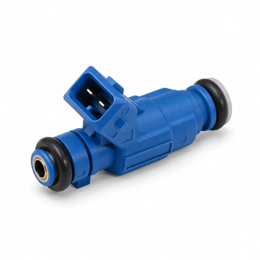
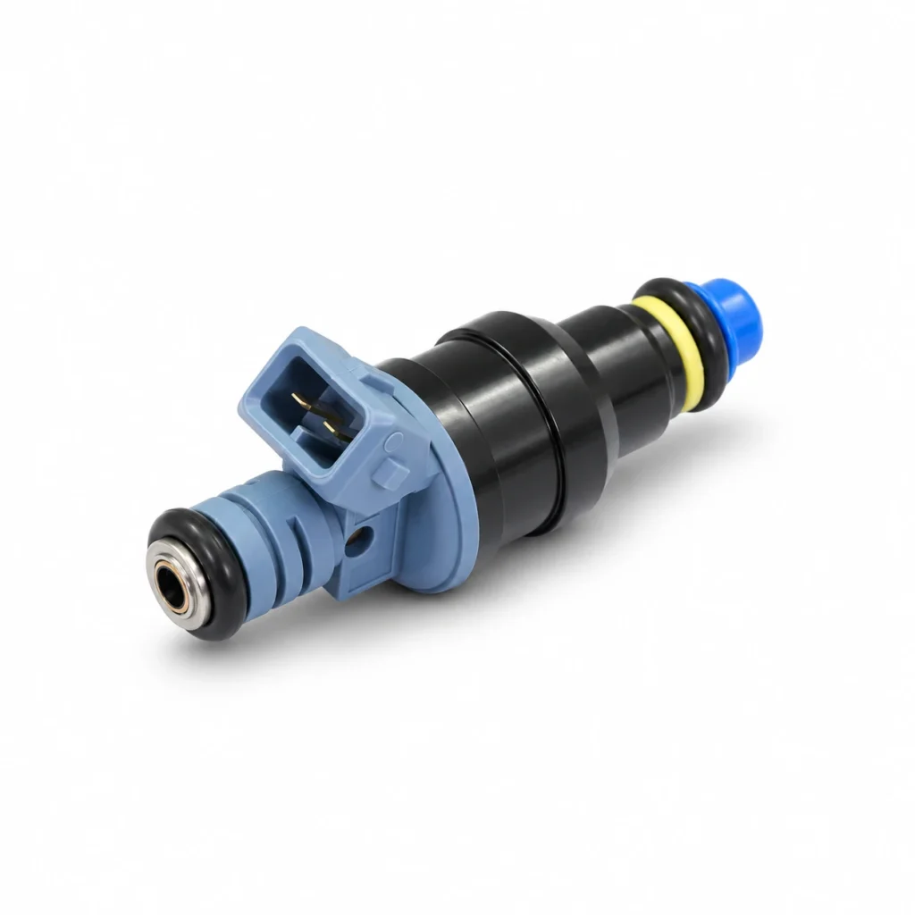
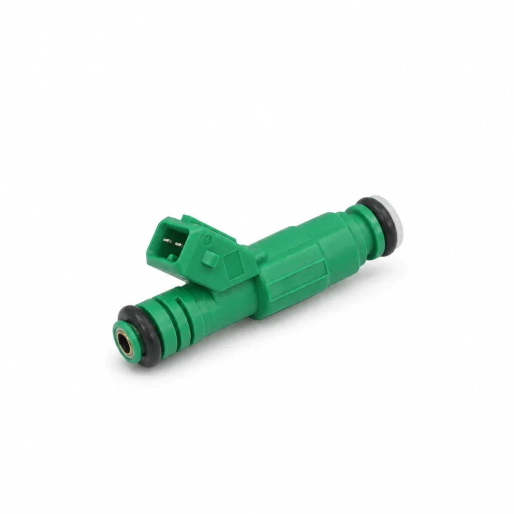
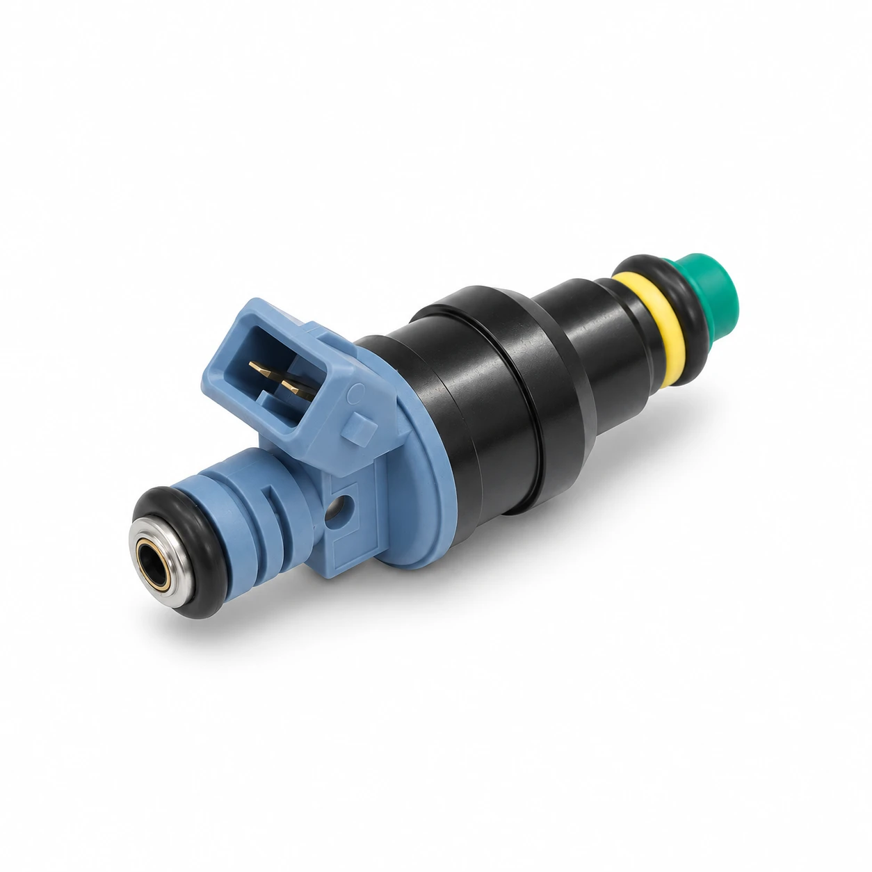
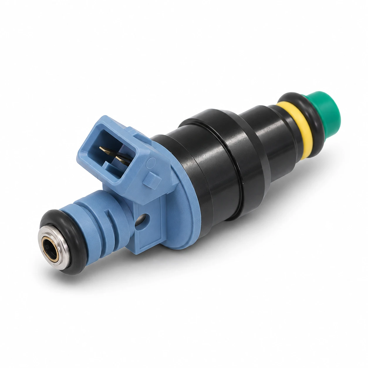
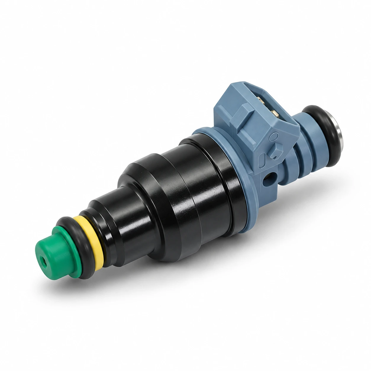
The site’s 0280150989 / 026133025 port-injector listing provides a real product reference for physical identification. Its photograph does not establish an offset table, flow rating, or compatibility with a particular driver. Those data must be obtained for the approved part and application.
Voltage compensation and pressure compensation are different checks
Voltage influences how quickly an injector responds electrically. If the voltage seen by the injector changes, the effective delay can change too. A calibration that behaves acceptably at one charging voltage can therefore show mixture errors at another. A change when electrical loads switch on deserves investigation, but it is not automatically proof that the dead-time table is wrong.
Measure and diagnose the supply path first. Compare the ECU’s reported voltage with an appropriate electrical measurement and check the grounds and wiring using the vehicle’s procedure. Entering compensation to hide a damaged connection can make the fuel model less accurate while leaving the actual defect unresolved. Stable electrical delivery and correct data are both necessary.
Pressure across the injector also matters. For port injection, the relevant hydraulic condition is the pressure difference between the fuel side and the discharge side, not an isolated rail-gauge number. A reference-pressure label must state what it means and use compatible units. Different regulator strategies can change how that differential behaves as engine conditions change.
The Emtron fuel-configuration documentation explains its dead-time table and the relationship with voltage and pressure. Use those instructions only for the corresponding controller setup. Another ECU may offer different table axes or perform another pressure correction elsewhere in its fuel model.
Understand the simple pulse-width model and its limits
A simplified illustration is: commanded pulse width equals effective fuel-delivery time plus the ECU’s offset. If an illustrative calculation needs 2.0 milliseconds of effective delivery and uses a 1.0 millisecond offset, the command would be 3.0 milliseconds. These are teaching numbers only, not values for any Kangsong injector or a recommendation for a real engine.
In that illustration, changing the assumed offset by 0.2 milliseconds is substantial relative to the 2.0 millisecond effective portion. At a much longer effective duration, the same absolute error is a smaller fraction of the delivery time. This explains why an offset mismatch can be conspicuous at light load even when a longer-pulse operating point appears acceptable.
The simplified addition is not a complete model at very short pulses. Minimum usable pulse width, non-linear delivery, driver behavior, and the ECU’s short-pulse correction can affect the result. Do not extend a straight-line equation into a region that the characterization data do not cover. A mathematically tidy spreadsheet cannot supply missing physical test results.
Read the data file before entering the values
| Data field | What to establish | Why it affects the transfer |
|---|---|---|
| Injector identity | Exact part, revision, and characterized configuration | A visually similar replacement may have different response |
| Offset definition | Effective net offset and the ECU’s interpretation | Different definitions can produce incorrect commanded time |
| Voltage axis | Units, measurement point, and supported range | Injector supply and reported ECU voltage may differ |
| Pressure condition | Differential pressure and reference convention | Rail pressure alone may not describe the test condition |
| Driver and fuel | Electrical driver type and test fluid | Characterization must represent the intended use |
| Short-pulse information | Minimum pulse and any non-linearity correction | Static flow and offset do not fully describe short events |
This checklist combines the data-definition issues described in the linked ECU documentation. It contains no proposed injector settings. The calibration team should approve the actual file, controller instructions, and application before values are transferred.
Pay particular attention to milliseconds versus microseconds. A unit conversion error can be much larger than the correction itself. Confirm axis order as well: a table transposed between voltage and pressure can look plausible while giving the wrong value at every operating point. Preserve the original file and record any conversions separately.
Keep impedance, flow, and latency in separate decisions
Electrical compatibility comes before calibration. The injector and ECU driver must be suitable for each other, including any required current control. The high-impedance injector guide explains that boundary. A compatible resistance does not establish correct flow or dead time, and an offset table cannot make an unsuitable electrical combination acceptable.
Static flow describes delivery under specified steady conditions. Dead time concerns the relationship between commanded time and effective delivery. Dynamic characterization describes behavior during pulsed operation. Those items complement each other. A supplier offering only a resistance measurement and one flow number has not automatically supplied everything needed to calibrate an aftermarket ECU.
The upstream fuel system also needs to maintain the intended operating conditions. Review the site’s return and returnless fuel-system comparison when determining how pressure is regulated. Do not compensate for an unstable supply by changing injector data until the hydraulic problem has been identified and corrected.
Validate the setup without tuning around a defect
Start with a saved baseline and a known, approved injector data set. Confirm the selected injector mode, fuel settings, voltage input, and pressure reference. Make one controlled change at a time and log the relevant conditions. An unexplained change in fuel trims is information for diagnosis, not permission to modify several unrelated tables simultaneously.
Validation should cover the conditions the calibration is expected to handle, using suitable equipment and a qualified calibration process. Compare behavior at different electrical loads and operating points while controlling other variables. Keep fuel temperature, engine temperature, pressure behavior, and sensor reliability in view. A correction that appears useful during warm idle can be misleading if another condition changed at the same time.
Do not derive a universal table from an idle experiment. Closed-loop control can mask an underlying error, and several different adjustments can produce a similar mixture reading at one point. The objective is a physically consistent model supported by measurements, not merely a screen that displays the requested air-fuel ratio for a few seconds.
Request a usable supplier package
For an inquiry, provide the vehicle or engine, injector reference number, controller model, driver arrangement, fuel, and intended differential-pressure range. Ask whether the supplied data were measured, converted from another format, or taken from an approved original source. Specify the required units and file format so the supplier does not send a table that the calibration team cannot interpret.
Include mechanical fit checks such as seal positions, connector keying, body length, and retention. The OEM fuel-system supply overview provides the business context, but an individual inquiry still needs component-specific documentation. Neither a general manufacturing description nor a product photo proves injector characterization.
Retain the accepted data revision alongside the purchase record. If the part, fuel, pressure setup, or controller changes later, reassess the data rather than silently reusing the old file. A clear link between part identity and calibration evidence prevents uncertainty when a replacement batch arrives months after the first installation.
Further learning: electrical command and injector response
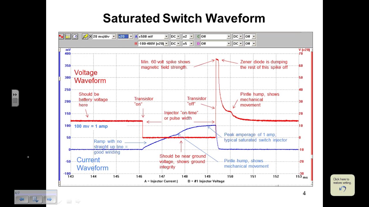
ScannerDanner: How to interpret fuel injector waveforms (a ScannerDanner Premium video)
ScannerDanner’s waveform lesson helps separate the electrical command from injector response. It supports understanding of the mechanism discussed here; a waveform lesson does not supply a complete offset table for an unidentified injector.
FAQ
Can I use dead-time data from another injector with the same resistance?
Matching resistance alone is insufficient. Confirm the exact injector identity, driver conditions, pressure reference, and the ECU’s data definition before using a characterization file.
Is dead time the same as injector flow rate?
No. Flow rate describes fuel delivery under defined conditions. Dead-time compensation accounts for response effects between the electrical command and effective fuel delivery.
Does a voltage-related mixture change always mean incorrect offset data?
No. Supply wiring, grounds, voltage measurement, pressure stability, and other operating changes can also affect the result. Diagnose those conditions before changing calibration data.
Can a product photograph establish the correct dead-time table?
No. A photograph supports physical identification. A usable table requires documented characterization for the relevant injector, operating conditions, and controller interpretation.