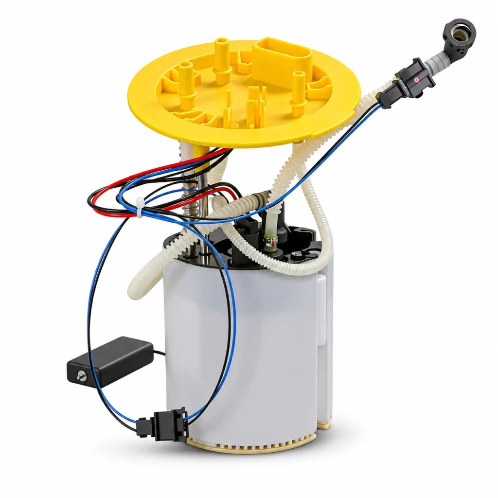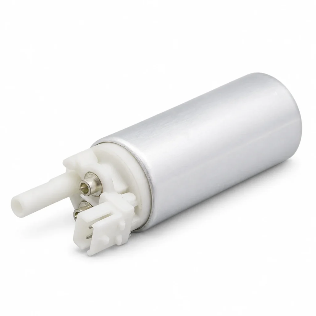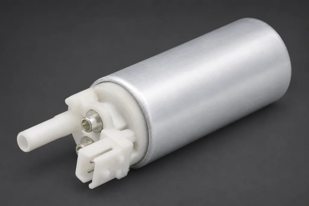
Fuel pump current ramp testing uses an oscilloscope and current clamp to examine how pump current changes over time. On a confirmed brushed DC pump, the ripple pattern can provide evidence about commutation, rotation, and intermittent operation that an average-current reading can hide. It does not replace the vehicle’s pressure, delivery, power-supply, or control checks, and the same interpretation must not be applied automatically to a brushless pump.
This guide explains what to record, how to recognize measurement mistakes, and how to calculate speed only when the waveform’s relationship to a full motor revolution is established.
What does a fuel pump current waveform show?
An average-current measurement compresses changing electrical behavior into a single value. A scope displays those changes against time. For a brushed motor, the brushes contact successive commutator segments as the armature turns, so current can have a recurring ripple structure associated with commutation.
Pico Technology’s brushed fuel-pump guided test explains this relationship and the importance of examining the repeating pattern. The guidance applies to a brushed-motor test; the segment count and normal operating values must still be established for the actual pump.
Current also responds to supply and load conditions. Changes in voltage, pump command, fuel pressure, or the hydraulic circuit can affect the trace. The waveform should therefore be interpreted alongside the circumstances under which it was recorded, rather than compared with an unrelated screenshot.
For a conventional meter reading and its operating conditions, our fuel pump current-draw guide covers the separate average-current question. Here, the useful extra information is the time-dependent pattern.
Capture a useful measurement before judging the pump
Confirm the motor, circuit, and operating state
Use the correct vehicle information to identify the pump, its feed, and its control arrangement. A shared circuit may carry other loads, and a vehicle can have more than one pump. Establish what current the selected measurement point actually includes.
Confirm whether the motor is brushed or electronically commutated. Also record whether the trace covers cranking, initial prime, warm idle, a commanded test, or the actual fault condition. A short prime event is not directly comparable to a continuously running pump under another load.
Use a suitable current clamp and protected access method
Follow the clamp and scope instructions for range, zeroing, connection, and orientation. An offset error can distort the apparent current level. An unsuitable range can hide small variations or clip the trace, while limited bandwidth or acquisition settings can obscure useful detail.
Clamp around the correct single conductor using an approved access method. Clamping around both the outgoing and return conductors can cancel their magnetic effects and produce a misleading result. Where a service procedure uses a fuse extension, retain the correct fuse and use properly rated equipment; do not replace circuit protection with an improvised unfused wire.
Keep the settings and the original capture
Record clamp scaling, current range, timebase, coupling, filtering, and sample settings with the trace. Save enough time to examine several repeat patterns, then zoom into a suitable section. A cropped image without scale or test conditions is weak evidence for a replacement decision.
A practical demonstration appears in Snap-on’s current-ramp training note. Its example settings and speed discussion concern the demonstrated situation. They should not be treated as universal pass values or proof that all pumps have the same number of commutator segments.
Patterns to investigate, and their limits
| Observed feature | What to investigate | Supporting evidence | Conclusion to avoid |
|---|---|---|---|
| Recurring uneven ripple | A repeatable motor-related variation, after excluding acquisition artifacts | Multiple cycles, correct motor identification, matching-condition reference and required circuit checks | Calling every small difference a failed pump |
| Intermittent current loss | Supply interruption, control behavior, connection fault, or motor interruption | Time-correlated supply, command, and symptom record | Assuming the motor is the only possible cause |
| Changed mean current | Different electrical or hydraulic operating conditions | Voltage, pressure, fuel and command information | Applying one current threshold to all vehicles |
| Unexpectedly flat or clipped trace | Clamp range, scaling, coupling, bandwidth, or display configuration | Verified instrument setup and a repeat capture | Declaring the pump healthy from a poor capture |
| Fast switching dominates the trace | PWM supply or electronic drive behavior | Correct control description and measurement location | Counting switching edges as mechanical revolutions |
This table organizes the investigation rather than supplying a visual pass/fail standard. A waveform may justify further testing without proving a particular internal fault. Hydraulic delivery and the electrical path still need the checks required by the application.
For example, a repeat dropout that coincides with a supply interruption points to a different investigation from a repeat anomaly with the prescribed supply and command verified. A short capture may miss an intermittent problem entirely. Document the conditions and the limits of the observation.
How to calculate pump speed from a valid pattern
Speed calculation requires a known relationship between the waveform and mechanical rotation. If you have identified the time for one complete motor revolution, the conversion is:
Motor speed (rpm) = 60,000 ÷ time for one revolution (milliseconds).
The factor 60,000 converts milliseconds per revolution into revolutions per minute. The fuel-pump current-ramping task sheet by James Halderman uses this relationship and calls for the pump’s operating specification and commutator information.
For an arithmetic example only, a verified full rotation taking 16 milliseconds gives 60,000 ÷ 16 = 3,750 rpm. This is not a normal-speed specification or a pass result. The calculated speed must be compared with the correct application data under the documented voltage, pressure, and operating condition.
If segment-related ripple frequency is known instead, use rpm = 60 × ripple frequency (Hz) ÷ segment events per revolution. For example, 500 correctly identified segment events per second and eight events per revolution also give 3,750 rpm. If the actual motor had ten events per revolution, the same measured frequency would give 3,000 rpm. An assumed segment count changes the answer.
Do not infer the count from a generic chart. A clearly identifiable repeat pattern or verified component information is needed. Electronic switching edges, phase commutation, and mechanical rotation are not interchangeable counts. A frequency function that locks onto PWM can report a precise number that answers the wrong question.
Why a brushless pump needs its own procedure
A brushless motor has no brush-to-commutator interface for this test to evaluate. Its supply or phase-current waveform reflects the particular electronic drive arrangement. Its relationship between electrical events and mechanical revolutions depends on the motor and control method.
Our electric fuel-pump operation guide provides the broader system context. Use the vehicle manufacturer’s brushless-pump diagnostic procedure where applicable, rather than transferring a brushed-motor segment-count rule.
Turn the waveform into a defensible repair decision
Start with the reported symptom and establish whether the captured event corresponds to it. Verify the instrument setup, the motor type, and the relevant circuit conditions. Then combine the waveform with the specified pressure, delivery, and control tests. A visually interesting trace should not become a parts order without that connection.
Where a connection or supply problem is suspected, the fuel pump electrical-connection guide covers the broader power-path assessment. If the required electrical conditions are absent, resolve that evidence before condemning a replacement motor.
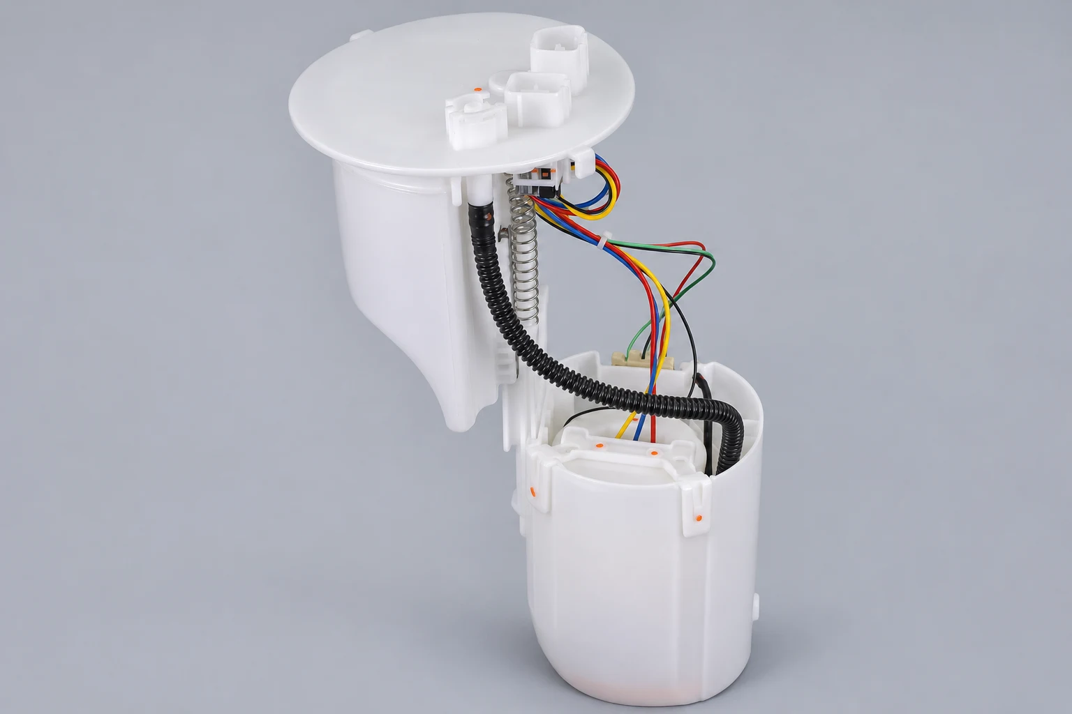
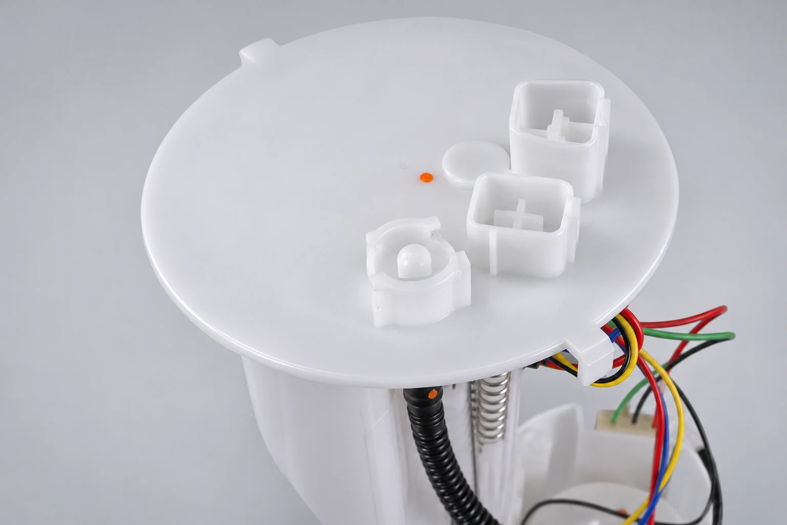
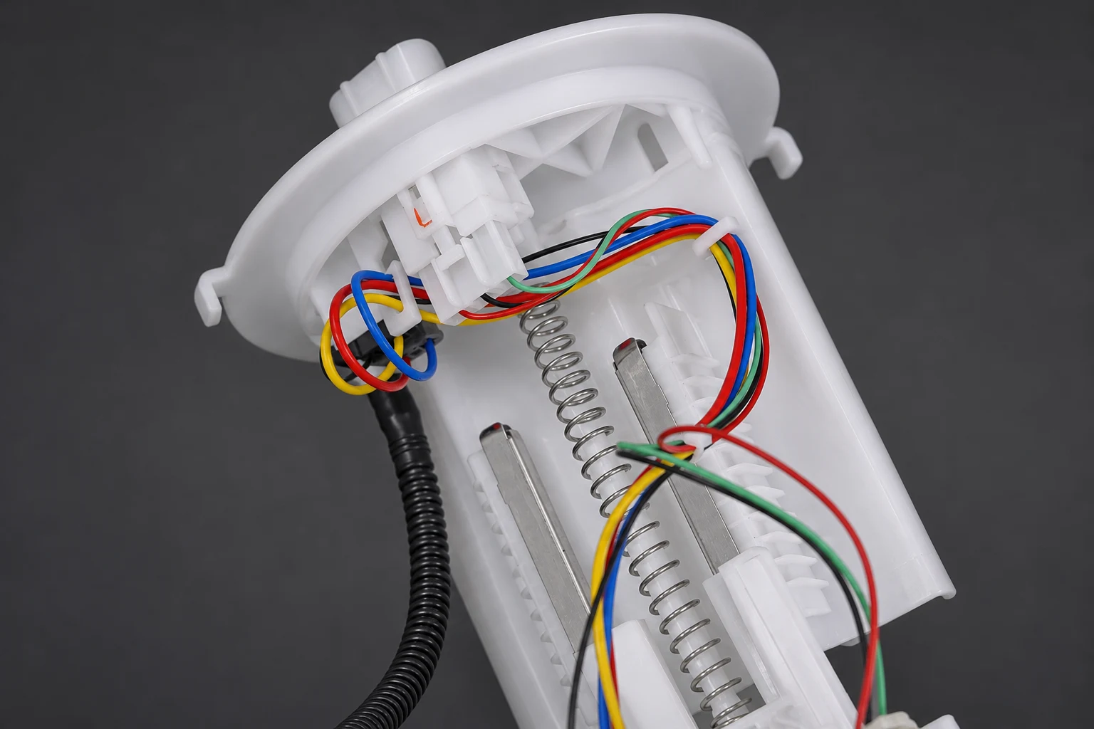
When the diagnosis establishes a pump-side fault, confirm the required replacement scope. The Kangsong Toyota Camry application module listing is a specific catalog reference for identification. Its photographs do not establish the motor architecture, an expected waveform, or the cause of a fault on another vehicle. Match the original reference and application before ordering.
Keep the original capture, settings, operating conditions, circuit findings, hydraulic results, and final diagnosis with the repair record. After repair, repeat the relevant checks and compare them under matching conditions. That gives the workshop and supplier a useful baseline if the complaint returns.
Testing must also respect fuel-vapor, electrical, and workshop hazards. The HSE motor-vehicle repair guidance covers fire, electrical safety, and other workshop risks. Use approved procedures and equipment; avoid improvised energized connections near fuel.
Watch: a current-ramp test demonstration
Snap-on Training Solutions demonstrates a fuel-pump current-ramp assessment using a scope and current probe. It is an equipment-training example on a particular vehicle. Use current vehicle data for segment count, settings, speed expectations, and the actual test method.

Watch the current-ramp training demonstration on YouTube.
Frequently asked questions
Is current ramp testing the same as measuring average amps?
No. A current waveform displays changes over time, while an average reading compresses those changes. Both require the correct operating conditions and application data.
Can I assume every pump has eight commutator segments?
No. Establish the actual relationship between ripple events and a full mechanical revolution. An assumed count can produce an incorrect speed calculation.
Does a normal-looking waveform prove fuel delivery is correct?
No. Pressure, volume, control, and circuit checks remain necessary as specified. A waveform is one part of the diagnostic evidence.
Can the brushed-pump calculation be applied to a brushless pump?
Not automatically. Brushless drive signals have a different interpretation. Use the appropriate vehicle and equipment procedure for the identified motor and controller.