When the vehicle commands power, electric fuel pump operation spins a pump motor so fuel is drawn from the tank and pushed toward the engine under pressure. On a modern vehicle that usually means a brief key-on prime, continuous run while the engine fires, a check valve that holds residual pressure after shutoff, and safety cutouts that open the power path when the engine stalls or a hard impact trips a shut-off switch. The pages that compare advantages or list every fitment stay elsewhere; this one stays on how the commanded path works.
For what a pump is for in the wider fuel system, see what a fuel pump is used for. Tradeoffs versus a mechanical pump live on advantages of an electric fuel pump. Diesel high-pressure stories and gasoline-platform notes have their own posts and are only soft-linked here.
What Electric Fuel Pump Operation Actually Means
Think in terms of a commanded path: electrical power spins a motor so fuel is drawn and pushed under pressure.
A cam-driven mechanical pump moves only when the engine turns. An electric pump has its own motor, so the vehicle’s electrical system can command fuel before the crankshaft spins and can keep commanding it as long as the control logic allows.
That command path—not a cam lobe—is the core of electric fuel pump operation. In plain language: when the pump gets voltage through a healthy circuit, the motor turns a pumping element, fuel enters through a strainer, and pressurized fuel leaves toward the filter, rail, or carburetor.
When that circuit opens, the motor stops. Everything else on this page—prime timers, check valves, inertia switches—is a refinement of that on/off command.
From Key-On to Continuous Run: The Control Sequence
The PCM primes the pump briefly, then keeps it powered while the engine runs and cuts it on stall.
On many fuel-injected vehicles, turning the key on wakes the powertrain control module. The PCM / fuel pump relay path then feeds battery voltage to the pump motor for a short prime window.
The motor runs for a few seconds to build pressure in the lines and rail. A timer limits that prime if the engine never starts, so the pump does not sit and push forever with the key on and the crankshaft still.
Once the engine is running, the pump usually stays powered for the whole drive. Older constant-speed pumps spin at one rate; many newer systems vary pump speed with load.
If the engine stalls, the PCM loses the RPM signal and drops the relay so the pump stops pushing fuel into a stopped engine.
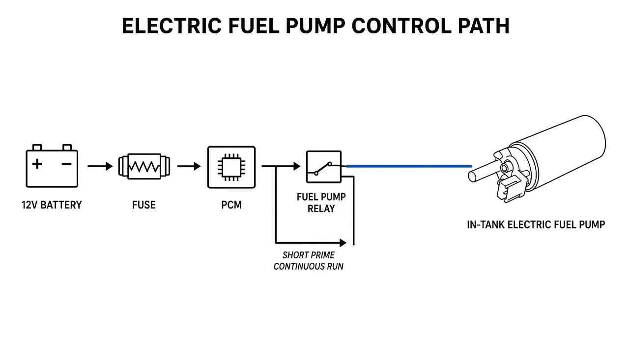
| Control state | What the electrical path does | What the pump does |
|---|---|---|
| Key on, engine not yet running | PCM energizes relay for a short prime window | Builds line/rail pressure, then stops if crank never comes |
| Engine running | Relay stays closed while RPM signal is present | Runs continuously (fixed or variable speed) |
| Engine stall | PCM sees lost RPM and opens the pump feed | Stops so fuel is not pushed into a dead engine |
| Hard impact (platforms with inertia switch) | Safety switch opens the pump circuit | Stops until the switch is reset |
That table is the operation story in four rows. Wiring details and conversion checklists belong in install notes, not here.
Motor and Pumping Elements Inside the Housing
Roller-vane, gerotor, or turbine impeller designs convert motor speed into fuel flow.
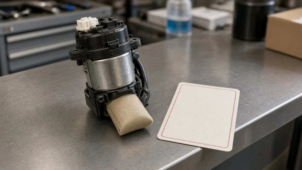
Inside the housing, brushes and a commutator (or a brushless driver on some designs) turn an armature. That shaft drives the pumping element.
The Roller vane / turbine impeller / gerotor family covers the common element classes. Older positive-displacement layouts use roller cells or roller vanes that trap fuel and push it from inlet to outlet.
Those roller designs often run around a few thousand rpm and may need a muffler in the line because the output can pulse. Gerotor pumps use an offset rotor pair, similar in idea to an oil pump, and typically run a bit faster.
Many newer modules use a turbine-style impeller ring that pushes fuel more smoothly. Independent technical libraries describe that turbine class spinning toward roughly 7,000 rpm and usually drawing less current than older roller designs.
Replacement pumps do not have to copy the original element geometry, but they do have to match the pressure and volume the engine expects. A quiet turbine that cannot hold rail pressure is still the wrong part for that job.
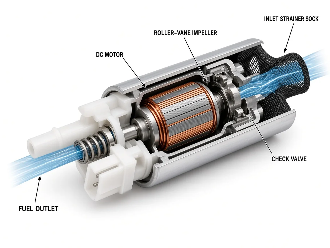
The cutaway above is only a teaching view of motor, element, strainer, and outlet path.
Pressure Bands, Check Valves, and Relief Paths
Port injection systems sit in a mid-pressure band; a check valve holds residual pressure after shutoff.
Independent technical summaries put many older port and throttle-body injection in-tank pumps around roughly 40–60 psi. Broader multiport application notes often cite about 30–85 psi depending on the system.
Those are class bands, not a single OE stamp for every vehicle. Too little pressure leans the mixture; too much can roughen idle and waste fuel.
Gasoline direct injection adds a second stage. The High-pressure fuel pump (GDI) on the engine is a separate mechanism from the in-tank electric supply pump.
The in-tank electric pump is often only a supply pump that feeds that separate high-pressure stage. The secondary stage can reach hundreds to a few thousand psi on the application bands cited in independent repair libraries.
That is still electric-supply operation plus a mechanical high-pressure stage—not a retelling of diesel injection-pump architecture.
| System class | Electric pump role | Pressure context (typical class) |
|---|---|---|
| Port / TBI feed | In-tank electric is the main pressure source | Often ~40–60 psi; multiport notes ~30–85 psi |
| Gasoline direct injection | In-tank electric supplies a separate HP pump | Supply pressure to the HP stage; HP stage much higher |
| Carburetor-era electric | Often lower-pressure diaphragm or low-pressure rotary | Must be regulated if dead-headed into a float bowl |
Fuel leaves the pump through a one-way check valve that helps hold residual pressure when the motor stops, so the next start does not begin from a fully collapsed rail. A Relief / release valve path limits over-pressure if flow is blocked.
Downstream, a Fuel pressure regulator on the rail (or inside a returnless module) keeps the injectors in their design window and, on return systems, sends excess fuel back to the tank.
In-Tank vs Inline Location in the Operation Story
Immersion cools the motor; inline units sit outside and still push fuel after drawing from the tank.
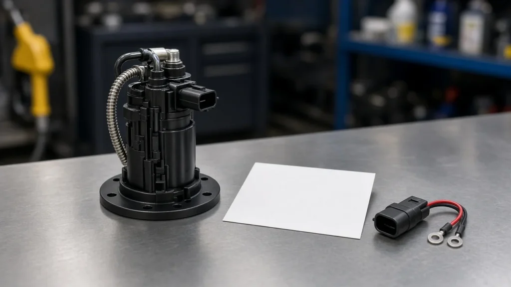
Most modern gasoline injection modules sit in the tank as an In-tank pump module with a strainer sock and a fuel-level sender. Liquid fuel around the motor cools and lubricates it.
Because the closed chamber is full of liquid fuel without free oxygen, the fire risk at the motor is lower than an open air-cooled spark in vapor. A submerged pump also does not have to pump air through dry lines after a tank drain or a line open the way a high-mounted suction pump would.
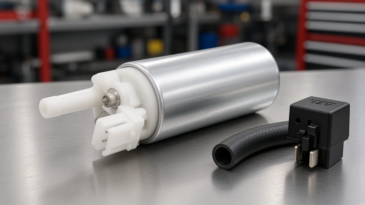
An Inline / external pump mounts outside the tank—often along a frame rail. It draws through a line, then pushes toward the engine.
Those external units are easier to reach, usually louder, and still live or die by voltage, filtration, and a clean inlet. Push is better than a long suction lift: hang an external pump high above the fuel level and it spends its life trying to lift instead of push.
Important: Running an in-tank pump with the tank near empty can leave the motor short on cooling and lubrication. Source: AA1Car — Electric Fuel Pumps: How They Work, Why They Fail.
Diesel high-pressure pump operation and gasoline-platform electric notes are covered on their own posts (diesel fuel pump operation, gasoline electric fuel pump) and are not retold here.
Electric Fuel Pump Safety Switch and Shut-Off Cutouts
An inertia safety switch, oil-pressure cutoff, or PCM stall logic opens the power path so the pump stops pushing.
Because an electric pump can keep moving fuel whenever it has power, the operation design includes ways to open that path. On many factory vehicles—Ford platforms are a commonly cited example—an electric fuel pump safety switch of the inertia type sits in the circuit.
A hard jolt trips the switch and opens the pump feed to reduce fire risk if a line is ruptured. After the impact event, the switch usually needs a manual reset button pressed before the pump will prime again.
Builders and owners talking about conversions ask the same question in user language: what about emergency shut-offs in an accident? A common answer on classic-car threads is an oil-pressure cutoff so the pump cannot keep running without oil pressure.
That oil-pressure device is one form of electric fuel pump safety shut off switch practice. The PCM stall cut already described is another. The shared idea is simple: when the vehicle is no longer in a safe run state, the commanded path must open.
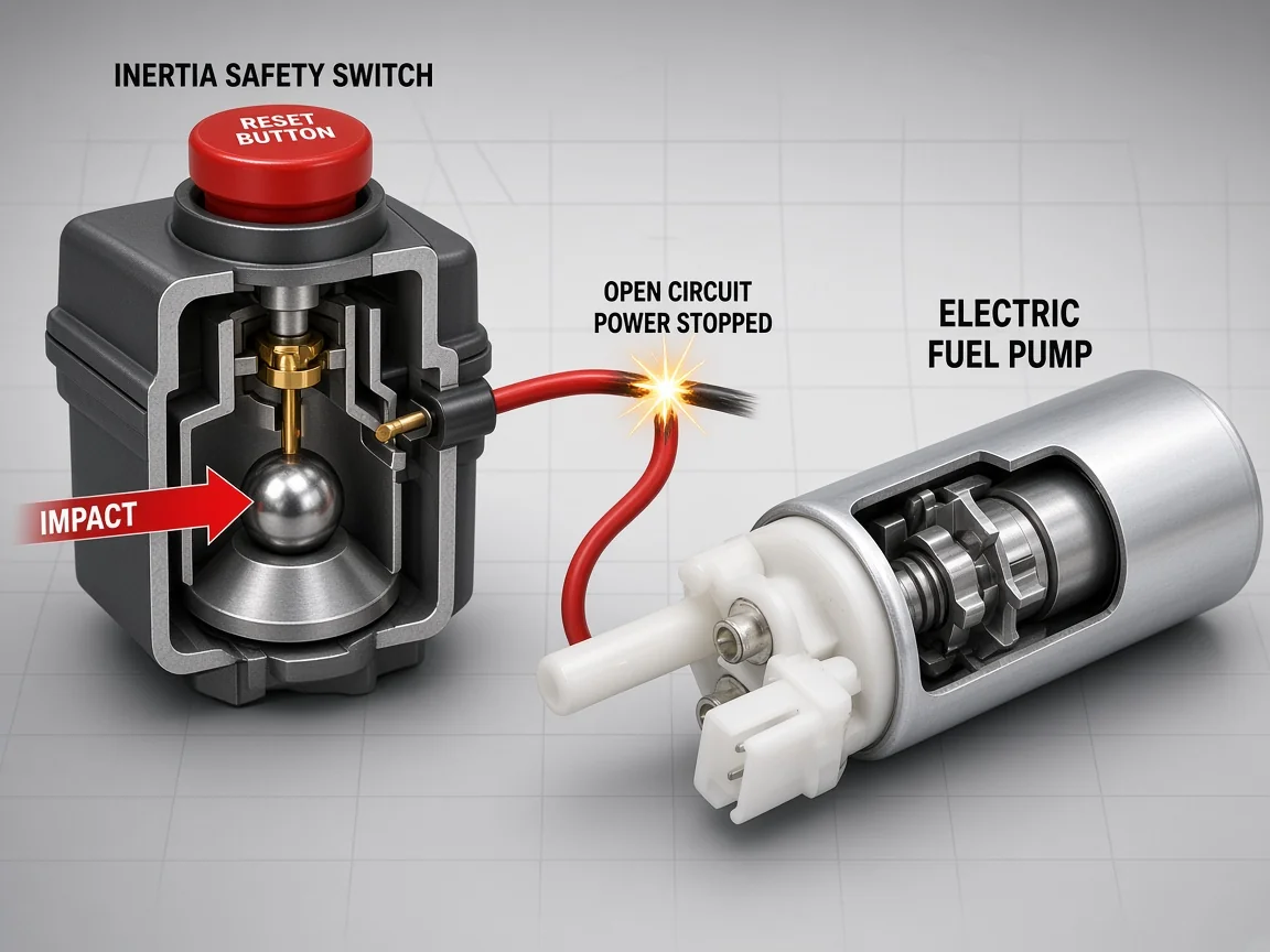
These cutouts are part of how electric fuel pump operation is supposed to stop—not a shopping list of brands. If a car cranks but will not start after a bump, checking whether an inertia switch has tripped is a diagnosis step that belongs to the same power-path story.
Older Solenoid-Diaphragm Electrics in Brief
Some older designs pulse a diaphragm with a solenoid instead of a high-speed rotary impeller.
Not every “electric fuel pump” in older literature is a submerged turbine. Some carburetor-era units use a solenoid that pulls a diaphragm down, then open a set of contacts at the end of travel so the diaphragm spring returns and the cycle repeats.
The valves and chambers look closer to a mechanical diaphragm pump; the difference is that electricity, not a cam, provides the stroke. When you read an older diagram with points and a solenoid, you are looking at that family—not the high-speed roller-vane or turbine module on a modern rail.
Scoped Electric Fuel Pump Product Kits on This Catalog
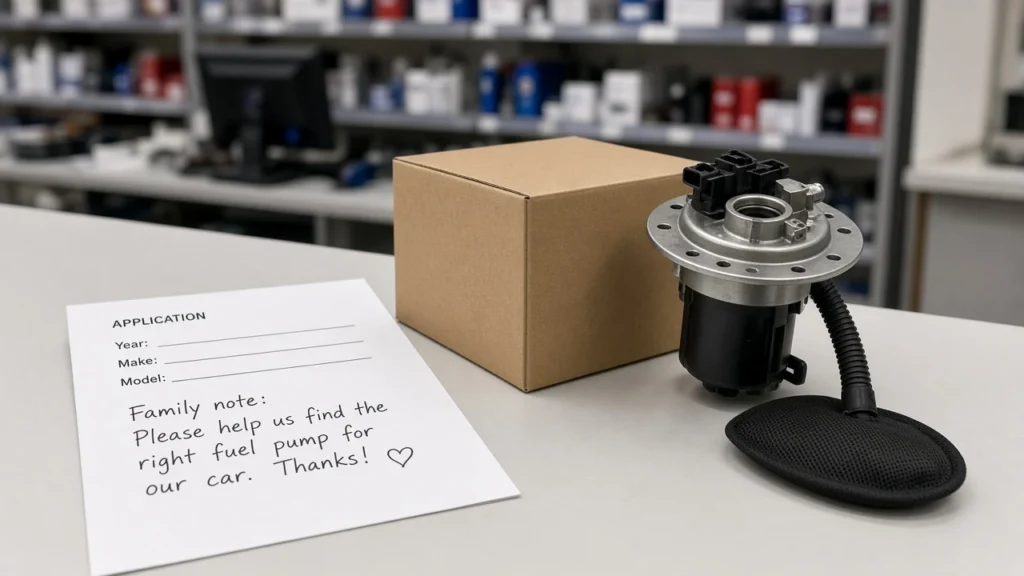
Match printed PDP applications for kits such as 2551/2552, then browse products-root—not a universal pump.
Operation knowledge tells you why voltage, filtration, immersion cooling, and shut-offs matter. It does not invent fitment. On this catalog, a light next step is a Kangsong electric gasoline kit with installation accessories when the printed applications match.
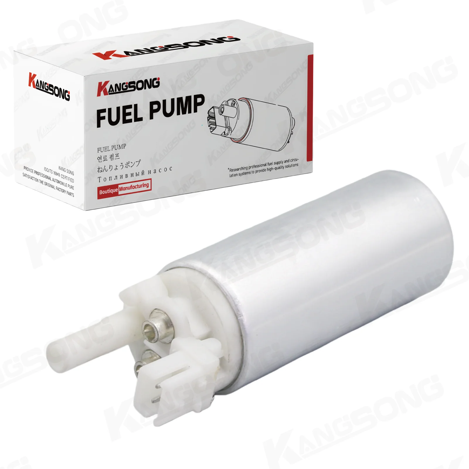
The electric gasoline fuel pump with installation kit (product 2551) lists OE-comparable harness and mounting provisions, GPH 43.3–49.5, maximum air pressure 12–26 on the PDP label, a 2-pin main connector, and a title scoped to 1987–1995 C/K pickup applications with OE crosses such as EP240, EP386, and 25168719.
A second live example, the Hyundai/Kia-compatible electric gasoline fuel pump (product 2552), publishes the same GPH and pressure bands under Accent I / Sephia title scopes. If those printed lines do not match the vehicle, browse the products catalog root instead of forcing a part.
This page does not rank advantages, size every platform, or claim brand equivalence. It only shows how the commanded pump works, then points at application-scoped hardware when the title already says so.
FAQ
Should an electric fuel pump run all the time?
No. Many systems prime briefly on key-on, then run while the engine is running.
If the engine stalls, control logic typically cuts pump power. A pump that stays live with the key on and the engine dead is a wiring or control fault, not normal operation.
What is an electric fuel pump safety switch?
Usually an inertia switch in the pump power path. A hard jolt opens the circuit so the pump stops; a reset button is often required before the next prime.
What is an electric fuel pump safety shut off switch?
It is the family of cutouts that open pump power when continued flow would be unsafe or pointless—inertia switches, oil-pressure cutoffs on many conversions, and PCM stall shutoff on factory EFI.
How does electric fuel pump operation build pressure?
Electrical power spins the motor and pumping element; fuel is drawn through a strainer and pushed toward the rail or carburetor. A regulator (or returnless module control) holds the system in its design band.
Why are many electric pumps inside the tank?
Immersion cools and lubricates the motor, keeps the chamber oxygen-poor around the windings, and avoids having to pump vapor through dry lines after service.
Does a check valve matter after the pump stops?
Yes. The outlet check valve helps hold residual pressure so the next start is not a long dry crank while the rail refills from zero.
How is GDI different for the in-tank electric pump?
On many direct-injection gasoline engines the in-tank electric pump mainly supplies a separate high-pressure pump. The high-pressure stage is a different mechanism and is not the same story as a diesel injection pump page.
Can a noisy pump still be working incorrectly?
Yes. External pumps often drone even when healthy. Voltage drop, a clogged filter, or a tripped safety switch can still leave you with a no-start or lean condition.