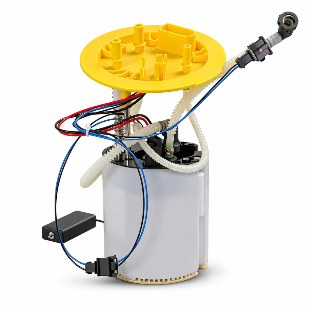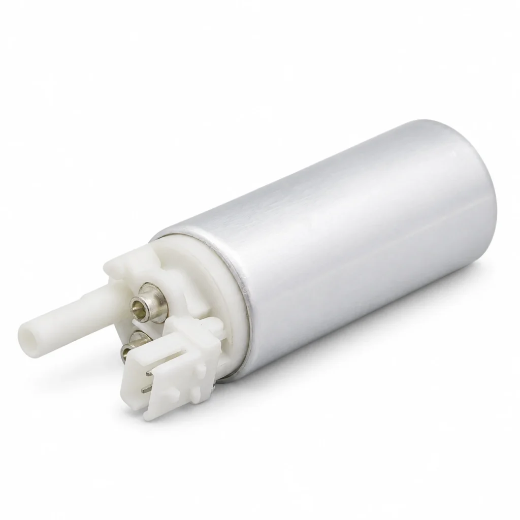
The main difference in a return vs returnless fuel system is where excess fuel is managed and how pressure is controlled. A return-type arrangement sends unused fuel from the engine-side circuit back to the tank. A returnless arrangement avoids that long engine-to-tank liquid return path, using tank-side mechanical regulation, electronic pump control, or another application-specific design. “Returnless” does not mean there is no regulator, no internal bypass, or no vapor plumbing.
For a replacement pump or module, the correct choice is the design specified for the vehicle. This guide explains the layouts, the identification evidence, and the compatibility questions that matter before buying parts.
How a return-type fuel system works
In a familiar port-injection return arrangement, the electric pump sends fuel toward the engine. A regulator controls the fuel-rail pressure and routes unused fuel back to the tank through a liquid return line. Supply, regulation, and return form a loop. The exact filter positions, pressure reference, and component locations vary with the vehicle.
Many conventional rail-mounted regulators use an intake-manifold reference. The purpose is to manage the pressure difference acting across the injector, rather than hold one identical gauge reading regardless of engine conditions. That behavior belongs to the specified system; it is not a rule for every regulator or every type of injection.
The return pipe carries liquid fuel. It should not be confused with a line used by the evaporative-emissions system. Both may be present near a tank, but they have different functions and must be identified from service information before any connection is disturbed.
If the question is how the pump itself moves fuel, our electric fuel pump operation guide covers that mechanism. The distinction here is the complete delivery-system arrangement surrounding the pump.
Returnless does not describe only one design
Mechanical regulation near or inside the tank
A mechanically regulated returnless arrangement can bypass excess fuel close to its source, rather than sending it through a long return circuit from the engine. A regulator may be incorporated in the tank module or another tank-side assembly. The engine-side supply therefore lacks the conventional liquid return loop even though fuel can still circulate locally.
This distinction explains why a single supply line does not prove that the pump is electronically speed-controlled. A mechanical regulator can perform the pressure-control function. Its setpoint, serviceability, and replacement scope are application-specific, and may not be adjustable.
An OEM-authored example appears in Toyota’s Engine Control Systems I training material, which describes a tank-side bypass regulator in its returnless example. It illustrates that particular arrangement; use current vehicle-specific service information for a replacement or test specification.
Electronic control of pump delivery
An electronically controlled returnless system can vary pump operation to match the required delivery. The control arrangement may include a driver module, pressure feedback, and application-specific commands or diagnostic signals. The pump motor, driver, sensors, and engine control software work as a system.
The SAE paper Demand Delivery System—Returnless Fuel Delivery identifies both mechanical and electronic approaches to returnless regulation. Its abstract also describes another demand-regulated implementation, illustrating why the word returnless alone is insufficient to specify the hardware.
Do not assume a pump that physically fits will respond correctly to another vehicle’s controller. Connector shape, electrical characteristics, pressure-control design, and calibration requirements need documented confirmation. A nominal voltage or free-flow rating does not answer all of those questions.
Return vs returnless fuel system comparison
| Feature | Conventional return-type | Mechanically regulated returnless | Electronically controlled returnless |
|---|---|---|---|
| Engine-side liquid return | Typically returns unused fuel from the regulated engine-side circuit | No conventional long return path from the rail; bypass occurs near the tank | No conventional long return path from the rail; delivery is managed by the specified control arrangement |
| Pressure-control evidence | Regulator location and reference, plus supply and return routing | Tank-side regulator and its documented setting or module specification | Pump controller, feedback and command strategy, plus any mechanical pressure-limiting provisions |
| Replacement information | Pump specification, regulator compatibility and line arrangement | Correct module, regulator scope, interfaces and application | Correct motor/module, controller compatibility, interfaces and any required calibration |
| Misleading shortcut | Assuming every two-line connection is supply plus return | Assuming one supply line means variable-speed pump control | Assuming an averaged meter reading proves inadequate power |
| Useful diagnostic record | Pressure under the prescribed conditions and the relevant regulator/return checks | Pressure and delivery against the specified tank-side arrangement | Commanded and actual values, electrical supply and control checks under the prescribed conditions |
The table compares common design patterns, not universal component locations. Confirm the actual vehicle diagram and procedure. Some systems combine features, so a label should never replace the application information.
Why manufacturers use returnless arrangements
Returning fuel from the engine area can transfer heat into the tank. Avoiding that long return path can reduce one source of tank heating and vapor generation, while removing some piping and connections. The U.S. EPA’s technical support document EPA420-R-00-023 discusses these benefits in its treatment of evaporative-emissions controls.
This is a design rationale, not proof that one layout is always better in every application. A factory fuel system also has to meet delivery, transient-response, durability, packaging, and control requirements. Its pump and regulator should be evaluated as parts of that engineered system.
Likewise, a return-type layout is not automatically required whenever engine demand rises. A properly specified returnless system may satisfy its intended application. For a modified vehicle, determine the complete system requirements and obtain a documented engineering solution rather than choosing a layout from a horsepower slogan.
Identify the actual layout before buying a pump
Start with vehicle identification, engine code, model year, market version, and the original pump or module reference. Obtain the correct fuel-system diagram. Similar vehicles may use different tank modules or control strategies, and earlier modifications can make a visual inspection harder to interpret.
Trace the liquid-fuel paths using the diagram. Establish which line supplies the engine and whether a separate line returns liquid from the regulated engine-side circuit. Do not disconnect unidentified hoses simply to see which one contains fuel. Evaporative plumbing, transfer connections, and tank ventilation must remain distinguished from the liquid return circuit.
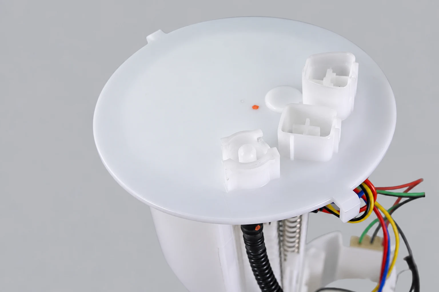
Next identify the pressure-control device and its location. A component on the rail may be a damper or sensor rather than a regulator. A module can contain features that are not visible in a product photograph. Use the parts information and service description to settle the identification.
Then establish whether pump output is controlled through a driver module or another specified arrangement. Wiring diagrams and diagnostic information are better evidence than wire colors or the number of hoses. If a driver fault is involved, our fuel pump control-module failure guide covers the separate diagnostic problem.
Finally, record the expected pressure at the specified test point and operating condition. A value from a different vehicle, or from another part of a direct-injection system, is not a valid comparison. On a gasoline direct-injection engine, the tank supply stage and engine-driven high-pressure stage remain distinct even when the low-pressure delivery is described as returnless.
What changes when specifying replacement hardware?
The pump element and complete module have different scope
A bare pump does not automatically include the reservoir, regulator, strainer, level sender, top flange, seals, or internal plumbing. Conversely, a complete assembly should not be assumed to include every component associated with fuel delivery. Confirm the itemized scope and the applicable original reference.
Our fuel pump assembly versus bare pump comparison explains that purchasing distinction. The return or returnless layout adds a system-compatibility question; it does not remove the need to identify the component being replaced.
The regulator and controller must match the application
For a mechanically regulated module, confirm the documented pressure-control specification and whether the regulator belongs to the replacement assembly. For electronic control, establish the intended controller and any required setup or calibration. Do not exchange one control arrangement for another because the flange fits the tank opening.
Where the inquiry concerns a separate pressure-control component, use the fuel pump pressure-regulator guide. This article compares system layouts rather than providing a universal regulator adjustment or replacement procedure.
Photographs help verify interfaces, not hidden performance
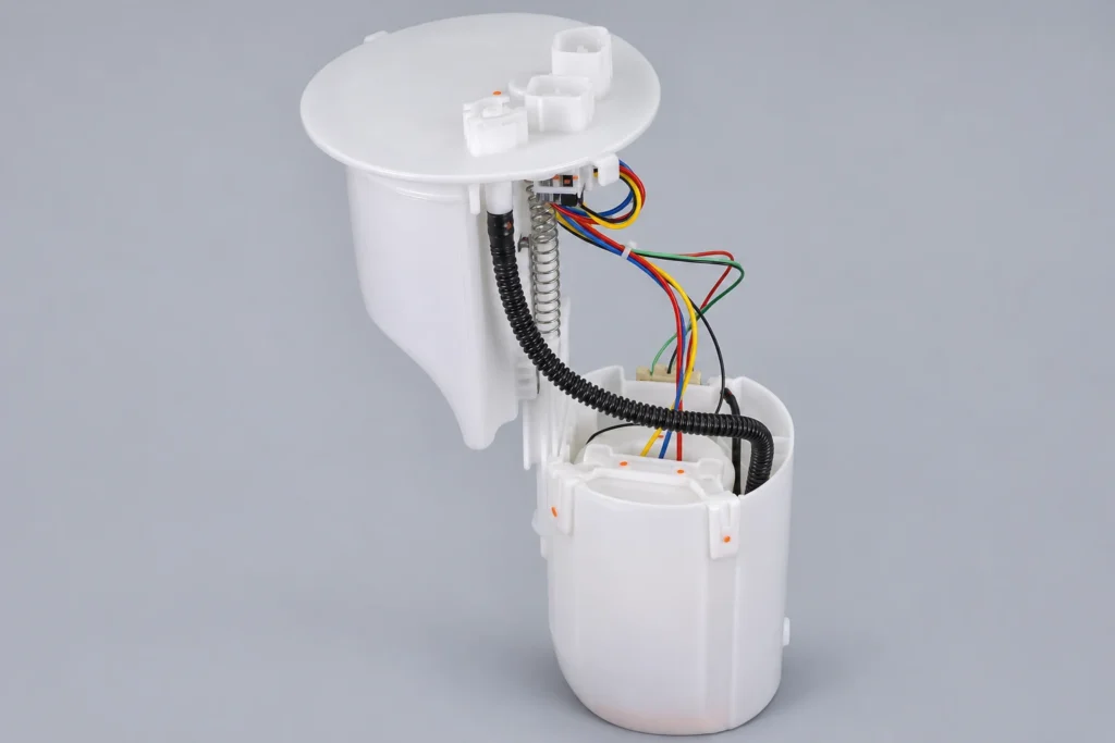
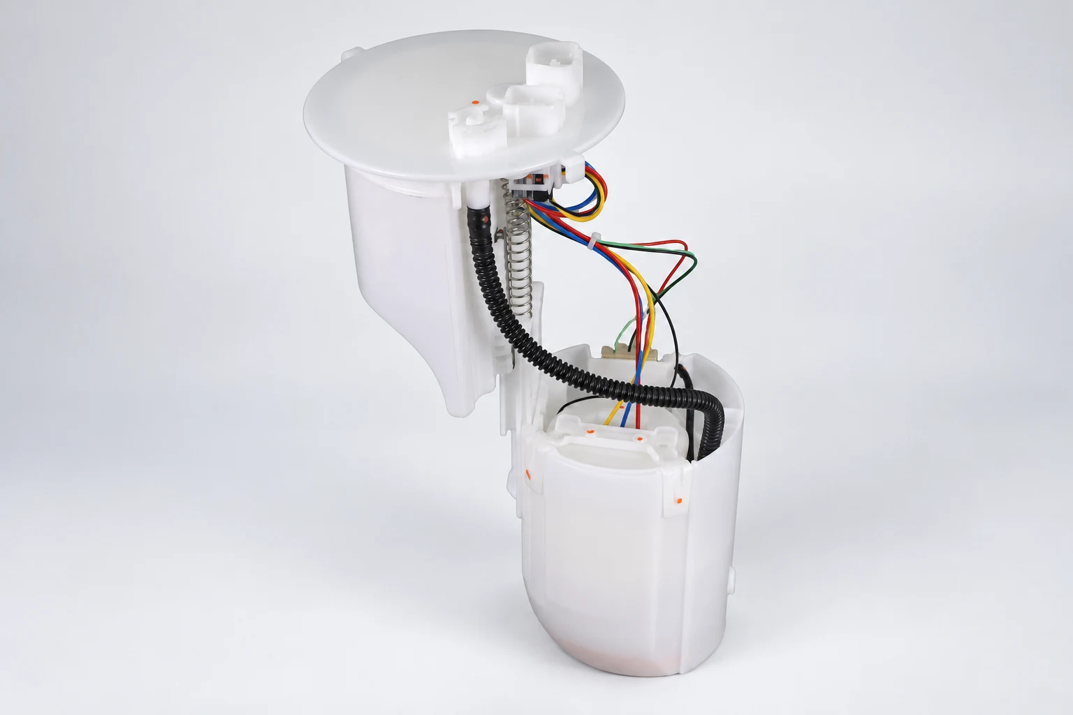
Kangsong’s Toyota Camry application fuel pump assembly listing provides an example of an application-specific module and visible interfaces. Confirm the vehicle’s original part number and current product documentation before ordering. The pictured unit is not presented as a universal returnless conversion kit.
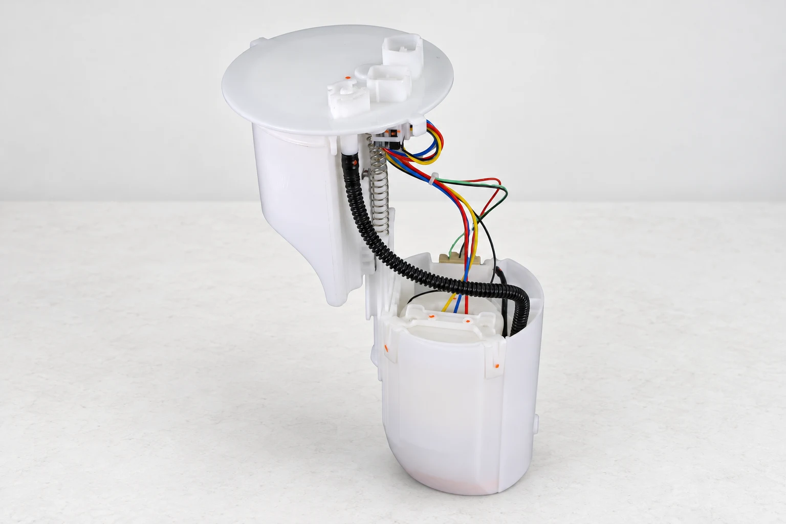
A useful supplier request includes the original reference, vehicle details, verified layout, regulator or controller information, and clear photographs of the flange and connections. Add the relevant service-test results when the request follows a fault. This prevents a delivery problem from becoming an unsupported assumption about which assembly to ship.
Can a returnless system be converted to a return system?
A conversion is a system redesign, not simply the addition of a hose. Pump compatibility, regulator selection, fuel-line routing, pressure reference, filtration, electrical control, calibration, fuel compatibility, and emissions requirements may all be affected. An approved replacement should preserve the original design unless a properly specified conversion is the actual project.
For routine repair, follow the vehicle’s service instructions, pressure-release method, fuel-handling precautions, and leak checks. Do not cap, bypass, or repurpose unidentified connections. A correct-looking installation still needs the prescribed pressure, delivery, electrical, and sealing verification before the vehicle is released.
Watch: the pressure regulator’s role
TechTrixInfo’s educational animation explains a fuel pressure regulator valve. It helps illustrate the regulating function discussed above, but does not represent every returnless design or provide settings for the pictured module.
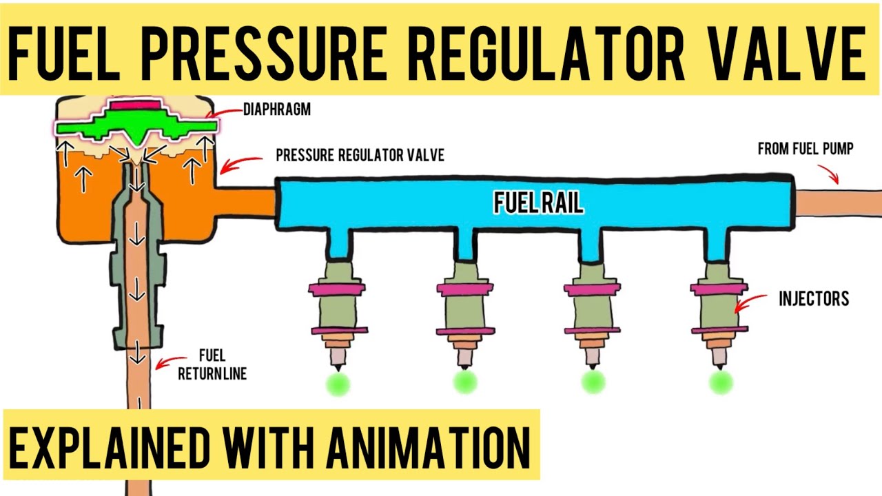
Watch the pressure-regulator animation on YouTube.
Frequently asked questions
Does returnless mean there is no fuel pressure regulator?
No. Mechanical returnless systems can regulate pressure near or inside the tank. Other arrangements use electronic delivery control. Identify the actual design from the vehicle documentation.
Is every returnless fuel pump variable-speed?
No. The absence of an engine-side liquid return does not establish how the pump is controlled. A mechanically regulated system can also be returnless.
Can I identify supply and return just by counting the tank connections?
No. Other connections may serve vapor handling, transfer, or different functions. Use the correct diagram and component information before assigning a purpose to a fitting.
Which system is better for a standard replacement?
The appropriate choice is the system specified for the vehicle. Match the pump or module, pressure-control arrangement, electrical compatibility, and original application rather than selecting a different architecture.