The conductors that feed the electric supply pump are the ones a diesel fuel pump wiring diagram is meant to show, while the injection pump often stays off that electric circuit. A counter in the United States marks those supply conductors before opening a year file. Later sections cover a 2001 dodge ram 2500 diesel search, a 2004 dodge ram 2500 diesel search, and the printed Freelander 2 2.2 diesel assembly that is a supply module rather than a Ram pump.
The electric supply conductors are the pump feed on the diagram
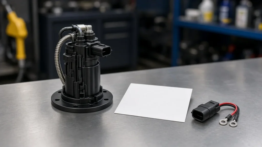
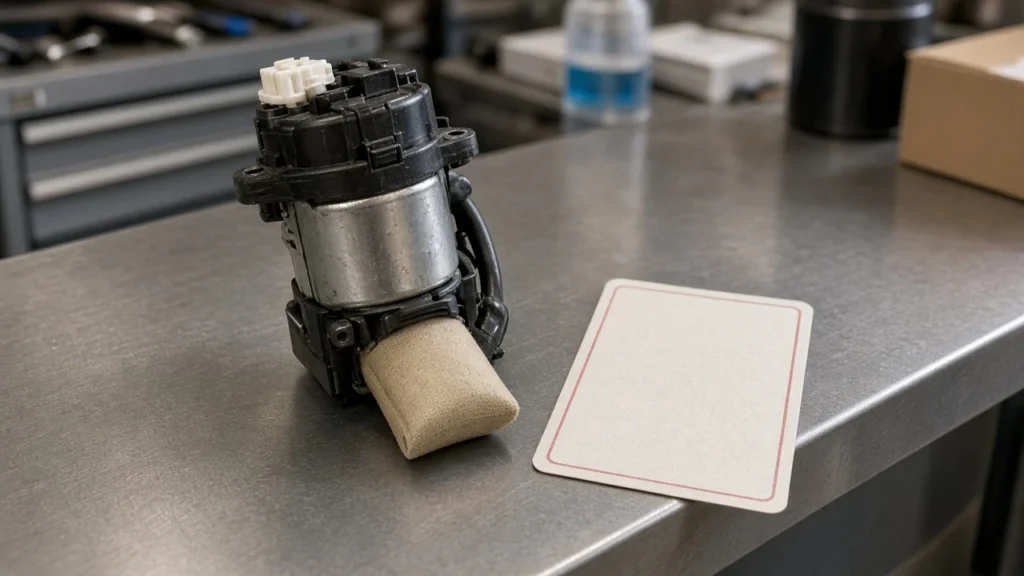
The electric supply conductors are the wires that power the lift pump, the electric supply pump that moves fuel out of the tank toward the injection hardware. The U.S. Department of Energy describes the fuel pump as the part that transfers fuel from the tank to the engine’s fuel injection system.
On a counter desk the diagram is a map of that transfer job. Feed and return for the electric motor are the pair to highlight first. Everything else on the page, including sender wires and controller pins, waits until those two conductors are identified.
A mechanical drawing of housings and gears answers a different question. Labels for that kind of sheet sit on the diesel fuel pump diagram page. Here the question is electrical: which conductors actually feed the pump motor.
| What you are looking at | What belongs to the electric supply circuit | What a counter does next |
|---|---|---|
| Electric supply pump | Motor feed and motor return | Mark that pair before quoting a module |
| Injection pump | Often gear- or cam-driven, outside this electric pair | Keep it off the supply-module line |
| Year sheet | The file for the truck year in the search | Open that year on its own |
| Printed supply assembly | Freelander 2 2.2 diesel lines on the product page | Use it only inside those printed lines |
Buyers sometimes arrive with a relay sketch from a general automotive post. That sketch can be a useful picture of a fused feed, and it is still not the vehicle sheet. The 12 volt fuel pump wiring article handles a generic gasoline relay layout, so this page stays with the diesel supply pair.
The injection pump usually sits off that electric drawing
The injection pump usually sits off that electric drawing because its job is to raise fuel for injection, often from gear or cam drive rather than from the supply-pump conductors. One common-rail layout drives a suction stage on the high-pressure pump, and the other uses an electric pump in the tank or on the frame rail.
MOTOR’s common-rail article describes low-pressure fuel reaching the high-pressure pump at approximately 55 to 70 psi. That figure belongs to the example in the November 2014 article. Ram quotes and Freelander 2 2.2 diesel quotes need their own figures, so this example stays with the MOTOR article.
Community speech on 24-valve trucks uses VP44 for the injection pump and lift pump for the electric supply pump. Cummins Forum readers are told to call the electric pump a lift pump and to call the VP44 an injection pump. Mixing the names is how a supply module gets quoted against injection-pump hardware.
The job split between those two pumps is already written up on the fuel pump versus injection pump page. What matters on a wiring sheet is narrower: if the conductors end at a motor in the tank, on the block, or on the frame, they are the supply circuit. If the device is the VP44 or another high-pressure pump turned by the engine, it is not that circuit.
High-pressure hardware for the injection side of the catalog is grouped on the high-pressure diesel fuel pumps hub. That hub is the injection family. The lift-pump wiring still comes from the year sheet in front of the counter.
A 2001 Ram 2500 diesel search opens that year’s sheet
A 2001 dodge ram 2500 diesel fuel pump wiring diagram search is a request for that year’s sheet, not for a color list written on a general page. Open the 2001 file the search is already pointing at, such as the factory service manual or the engine wiring map owners trade on the Cummins boards.
From the field: Tommy49 asked for a 2001 Dodge Cummins Ram diagram because there was no power to both pumps and the relay kept clicking, and staff split that click from the stock lift-pump pigtail on the ECM — 2001 Cummins pump thread.
A 2001 owner asked for a wiring diagram because there was no power to both pumps and the relay kept clicking. Staff on that thread split the clicking relay, which they tied to the VP, from the stock lift-pump pigtail that comes from the ECM.
Those are two controller outputs. A quote that treats them as one plug will miss the pump that actually moves fuel.
Live overview text for this search offered typical wire colors, a pressure band, and a suggestion to abandon the factory harness. None of that is reprinted here. Colors and cavities change by harness and by who rewired the truck, and a published overview is not the 2001 sheet.
When the truck has an in-tank conversion or an added pump, the original pigtail may only be a trigger. The counter still starts from the year sheet, then asks how the pump on the truck is actually tied in. An aftermarket harness compared with the vehicle plug is the subject of aftermarket fuel pump wiring, and that comparison is not repeated here.
A 2004 Ram 2500 diesel search opens a different year’s sheet
A 2004 dodge ram 2500 diesel fuel pump wiring diagram search opens a different year’s sheet from the 2001 file. The counter pulls the 2004 diagram on its own, even when the truck is still a 5.9 Cummins Ram 2500 and the words on the search look almost identical.
A Ford-truck owner learned that the diagrams posted for the pump circuit were for a 2004, and fuse numbers differ outside that year window. The lesson travels even though the truck brand does not.
A sheet dated for one build tells you the fuse and the connector for that build. The next model year’s fuse position can move while the pump motor looks the same in a photo.
Overview text for the 2004 search named cavities and wire colors. Those details stay off this page. If a buyer needs cavity numbers, the source is the 2004 wiring manual the search already surfaces, read as a document, not as a sentence copied into a product quote.
People also ask how to get a Cummins wiring diagram. The practical answer on the forums is the year file, often the factory service manual chapter for wiring, sometimes a member-posted engine map for 2001 specifically.
A 2004 buyer uses the 2004 file. Sharing one screenshot between the two years is how fuse and connector notes get crossed.
A controlled feed shows power, ground, and a trigger as different lines
Power, ground, and the trigger are three different lines on a controlled electric-pump drawing. Power is the conductor that brings battery voltage to the motor once a switch closes.
Ground is the return. The trigger is the smaller circuit that tells the fuel pump relay or the ECM to close that switch.
On EPA 2010 and later MaxxForce DT, 9, and 10 engines, key-on lets the ECM close the fuel pump relay so battery voltage reaches the electric pump, and the pump then stops if rotation is not detected. That pattern is for those MaxxForce engines.
It shows why a diagram can have a relay coil, a relay contact, and a pump motor as separate pieces. Ram pin names stay on the Ram sheet.
Some sheets place an inertia switch in series with the pump feed so a collision can open the circuit. Reading that device, and telling it from an oil-pressure switch, is covered on the fuel pump safety switch wiring page. On the diagram in front of you, the only task is to see whether that switch sits in the motor feed or only in the relay coil.
A straight run from the battery to the pump motor skips the trigger the sheet was drawn to show. This page does not describe a jump, a splice, or a bypass. If the motor is quiet while the connector still shows supply voltage, the return path and the connector itself are the next marks on the same sheet, which is the situation owners describe when the pump runs only on a separate pair of leads.
Wire gauge, fuse amperage, and brand-pump current charts showed up in the live results. They are left out. A counter who needs a gauge or a fuse value takes it from the year sheet or from the pump’s own instructions, not from a blended overview.
A Freelander 2 2.2 diesel assembly fits only that printed supply job
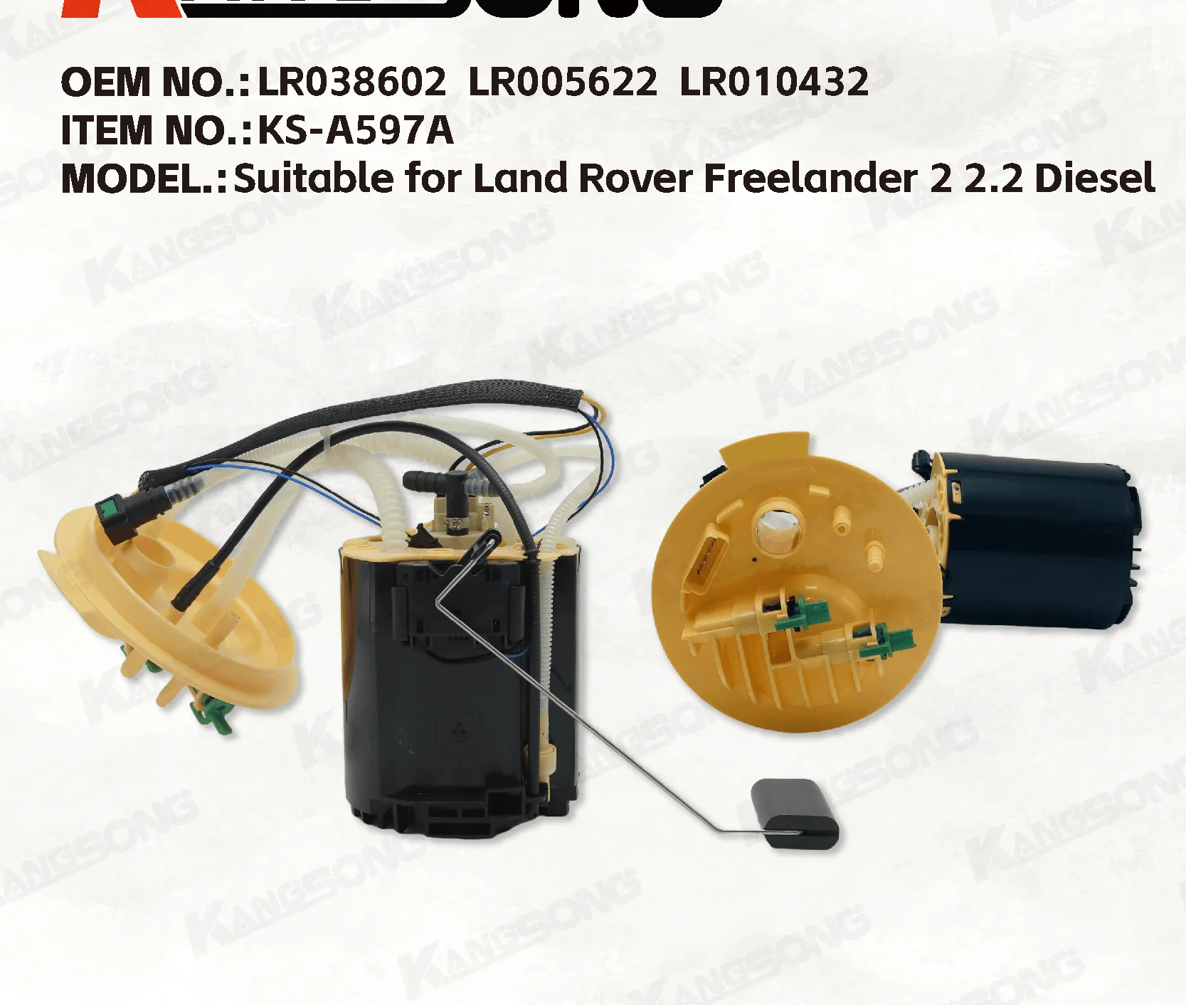
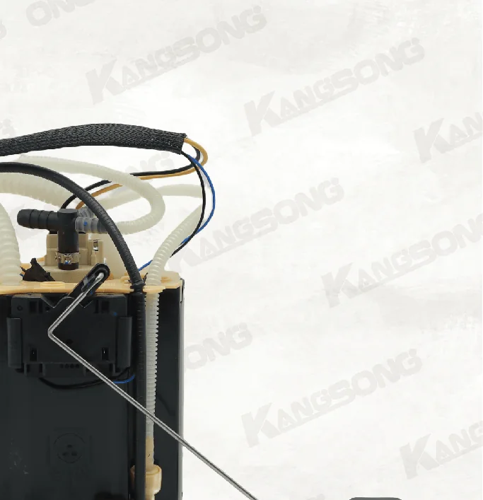
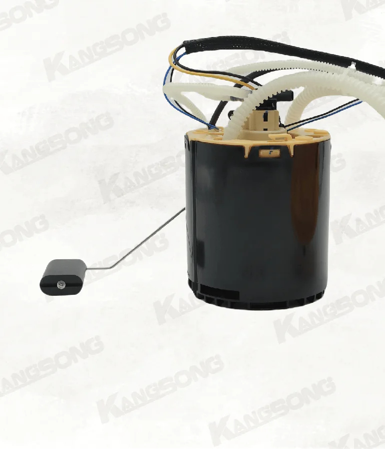
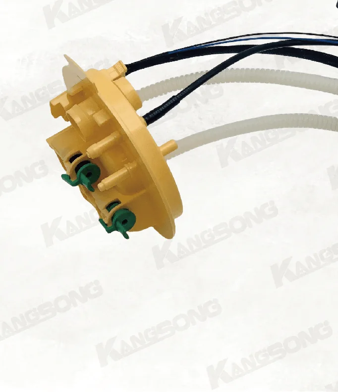
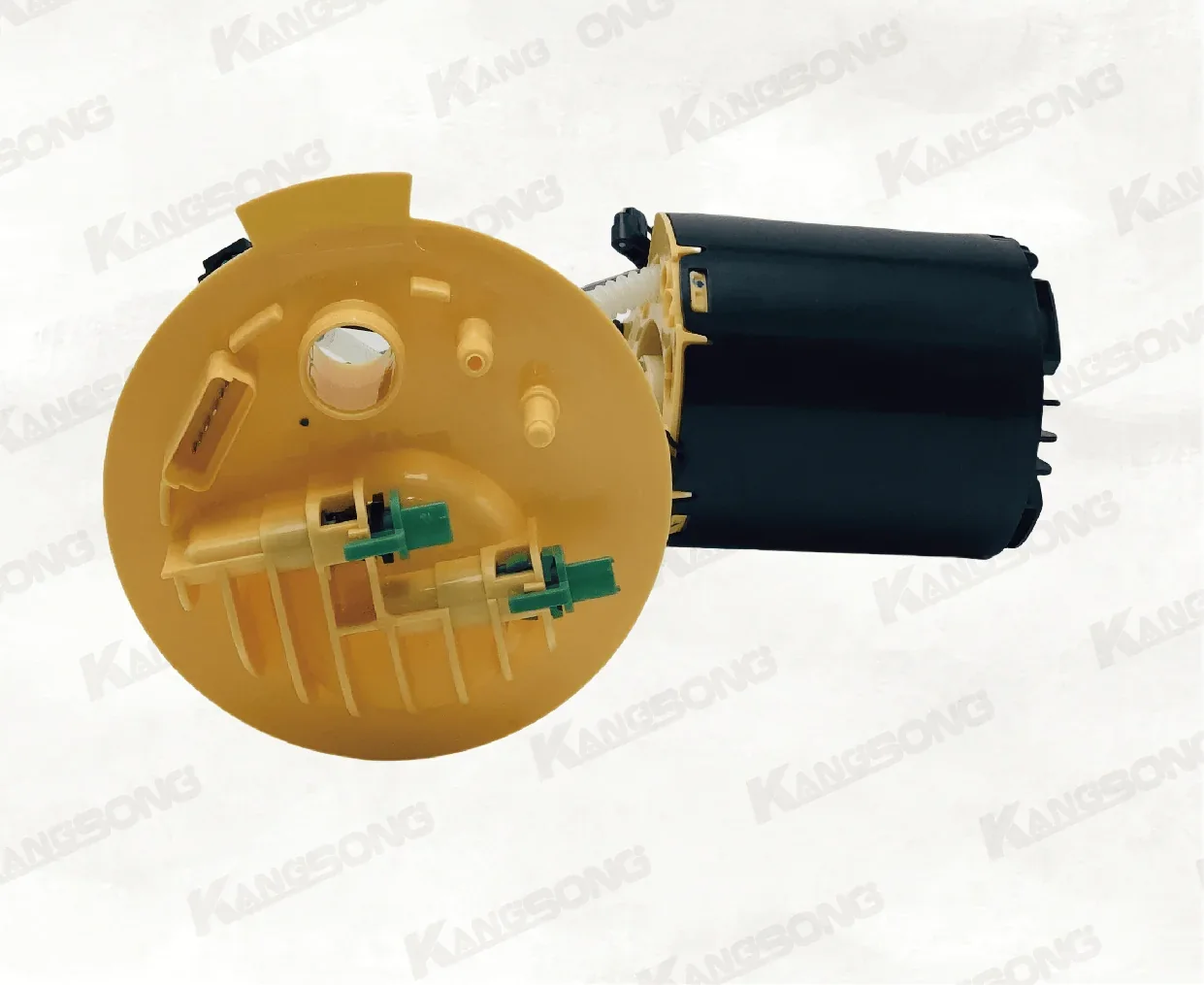
The printed Freelander 2 2.2 diesel assembly fits only the supply-module job on its own page, and only for the vehicle lines printed there. It is a fuel pump assembly, the electric supply hardware. A Ram lift pump is different hardware, and so is the injection pump.
The live title reads Applicable to Land Rover Freelander2 2.2 Diesel, with OE strings LR038602, LR005622, LR010432, LR010434, LR029279, and assembly code KSA597A. The overview repeats LR010434 and LR029279. Match those strings to the unit in hand before the assembly is offered as the supply module.
| Printed application | Printed engine detail |
|---|---|
| Land Rover Freelander 2 2014 Diesel 2.2 SD4 4×4 AWD | L359, 2179cc, 140KW, 190HP, 224DT |
| Land Rover Freelander 2 2014 Diesel 2.2 TD4 4×4 AWD | L359, 2179cc, 118KW, 160HP, 224DT, DW12BTED4 |
| Land Rover Freelander 2 2013 Diesel 2.2 SD4 4×4 AWD | L359, 2179cc, 140KW, 190HP, 224DT |
| Land Rover Freelander 2 2013 Diesel 2.2 TD4 4×4 AWD | L359, 2179cc, 115KW, 156HP, 224DT |
| Land Rover Freelander 2 2012 Diesel 2.2 TD4 4×4 AWD | L359, 2179cc, 115KW, 156HP, 224DT |
The Freelander 2 2.2 diesel fuel pump assembly is the page that carries those lines. A Ram 2500 search, whether 2001 or 2004, does not land on this assembly. When the job is some other vehicle, start from the product catalog and match a different printed window.
Installation still belongs with someone who works on that vehicle. The product notes ask for a professional install and for the year, brand, and model to be checked against the part number before purchase. That is a fitment step on the supply assembly, not a wiring recipe for a Ram harness.
FAQ
What color wires go to the fuel pump?
The year sheet for that vehicle carries the colors. A search overview is not that sheet, so this page does not print a Ram color list or a cavity chart.
Can I wire a diesel fuel pump straight to the battery?
The sheets discussed here show a controlled feed through a relay contact or a controller output. A straight battery connection is a different circuit, and this page does not give a jump, splice, or bypass procedure.
What happens if the electric supply pump is connected backwards?
Polarity belongs to the electric supply pump on the year sheet. Swapping the motor feed and the motor return is an electrical mistake on that pump, and those two conductors are not the injection pump.
Can you show a wiring diagram for a 4-wire fuel pump?
A four-wire module often carries the pump motor pair plus a fuel-level sender pair. The diagram separates those jobs. This page does not assign pin numbers or cavity letters.
Is the VP44 on the same electric circuit as the lift pump?
No. On these trucks the lift pump is the electric supply pump, and the VP44 is the injection pump. Forum replies treat the VP relay and the lift-pump pigtail as different controller outputs.
Does a 2004 Dodge Ram 2500 diesel sheet match a 2001 sheet?
No. Each search opens its own year file. Fuse positions and connector notes from one year are not assumed to sit in the same place on the other year.
Is the Freelander 2 2.2 diesel assembly a Ram lift pump?
No. It is the supply assembly printed for the Freelander 2 2.2 diesel lines in the table above. A Ram lift pump, and the injection pump, are different hardware.
References
- MaxxForce electric fuel pump diagnostic bulletin, NHTSA file SB-10055001-4261
- How diesel vehicles work, Alternative Fuels Data Center
- Diesel fuel systems, MOTOR, November 2014
- Fuel pump wiring diagram thread for a 2001 Cummins Ram
- Wiring diagram request for a fuel pump circuit, Ford-Trucks.com
- Lift pump versus VP44 naming on a Ram wiring request, Cummins Forum