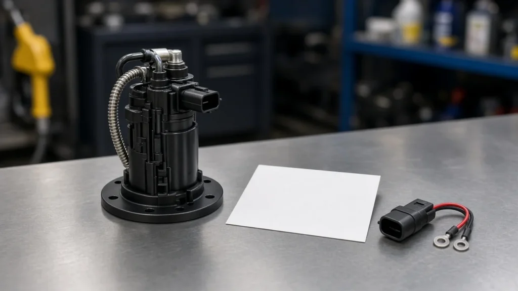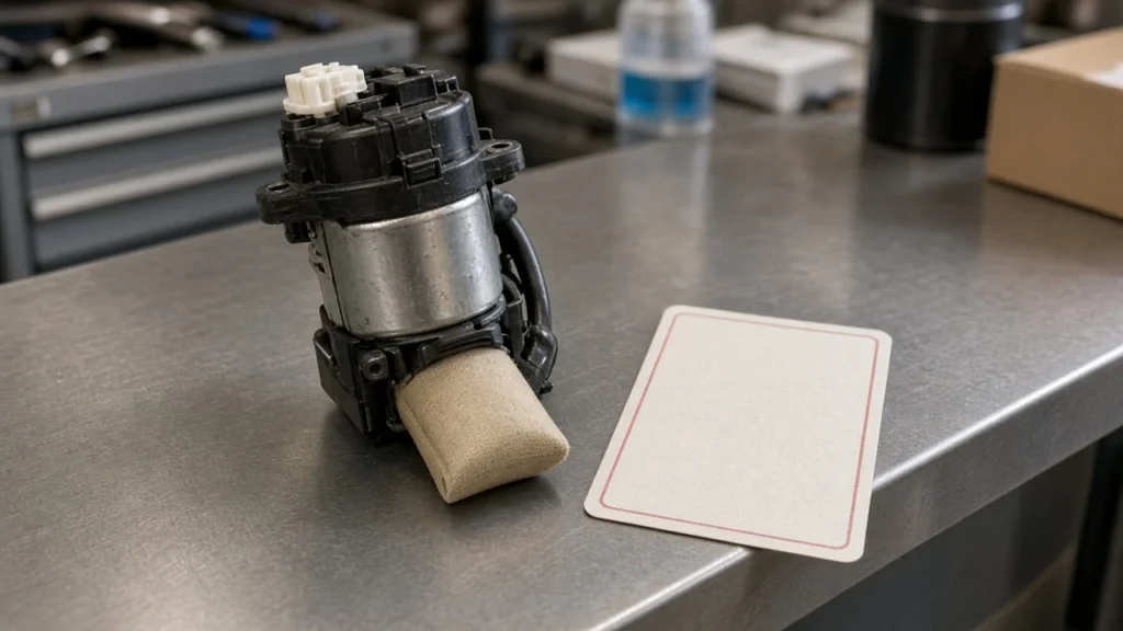
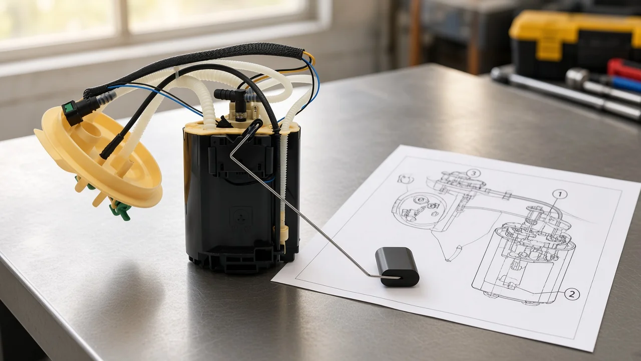
A diesel fuel pump diagram is the labeled drawing that shows how diesel moves from the tank through filters and the injection or supply pump to the injectors, plus the return paths that keep the circuit stable.
This page teaches how to read those labels across mechanical and common-rail families. You will see how numbered flow sheets work, how in-line and distributor drawings differ, where common-rail schemes change the story, and which Freelander 2 2.2 Diesel assembly page is safe to open after the drawing.
For pump-family naming without the drawing focus, see diesel fuel pump types. For a plain definition of the hardware, see what is a diesel fuel pump. An inline fuel pump diagram article is not live yet, so that sister page stays unlinked for now.
What a diesel fuel pump diagram actually shows
It maps tank-to-injector fuel paths and the pump parts that create pressure and meter delivery.
On a classic pump-line-nozzle layout, the diesel fuel injection pump diagram is the sheet that shows pressure created in a pumping element, a pulse traveling through a high-pressure line, and spray leaving the nozzle. DieselNet describes that three-stage chain as the defining shape of P-L-N systems.
A mechanical diesel fuel pump diagram often focuses on the injection pump itself: plunger and barrel pairs, a control rack, a helix, delivery valves, and the cam that drives the stroke. Helix-controlled pumps both meter fuel and create injection pressure, which is why the geometry on the plunger matters as much as the inlet arrow.
Common-rail sheets shift the emphasis. The high-pressure pump still matters, but the shared rail and electrically timed injectors share the page with the low-pressure feed path. The drawing is still a diesel fuel pump diagram; the architecture inside the boxes has changed.
How to read numbered diesel fuel-system flow diagrams
Match each callout to its stage, and keep micron and bar figures on the engine family printed on that sheet.
Start at the tank and follow the arrows. On a Detroit DD15 Version Five description, the low-pressure gear pump is callout (4), fuel leaves the tank, passes a shutoff in the feed line, and enters the filter module before returning through the gear pump loop.
Filter callouts are easy to over-generalize. That same DD15 sheet says the prefilter removes particles greater than 100 micron, while the water separator and final filter remove fine contaminants greater than 2 microns. Those micron figures belong to that Version Five module, not to every diesel filter bowl you see in a stock photo.
Pressure callouts need the same discipline. On that DD15 flow, the high-pressure fuel pump pressurizes fuel up to 900 bar (13,053 psi) before the rail, and the pressure limiting valve is described with leakage at 1075 bar and opening at 1250 bar. Quote those numbers as that sheet’s relief story, not as a universal diesel rating.
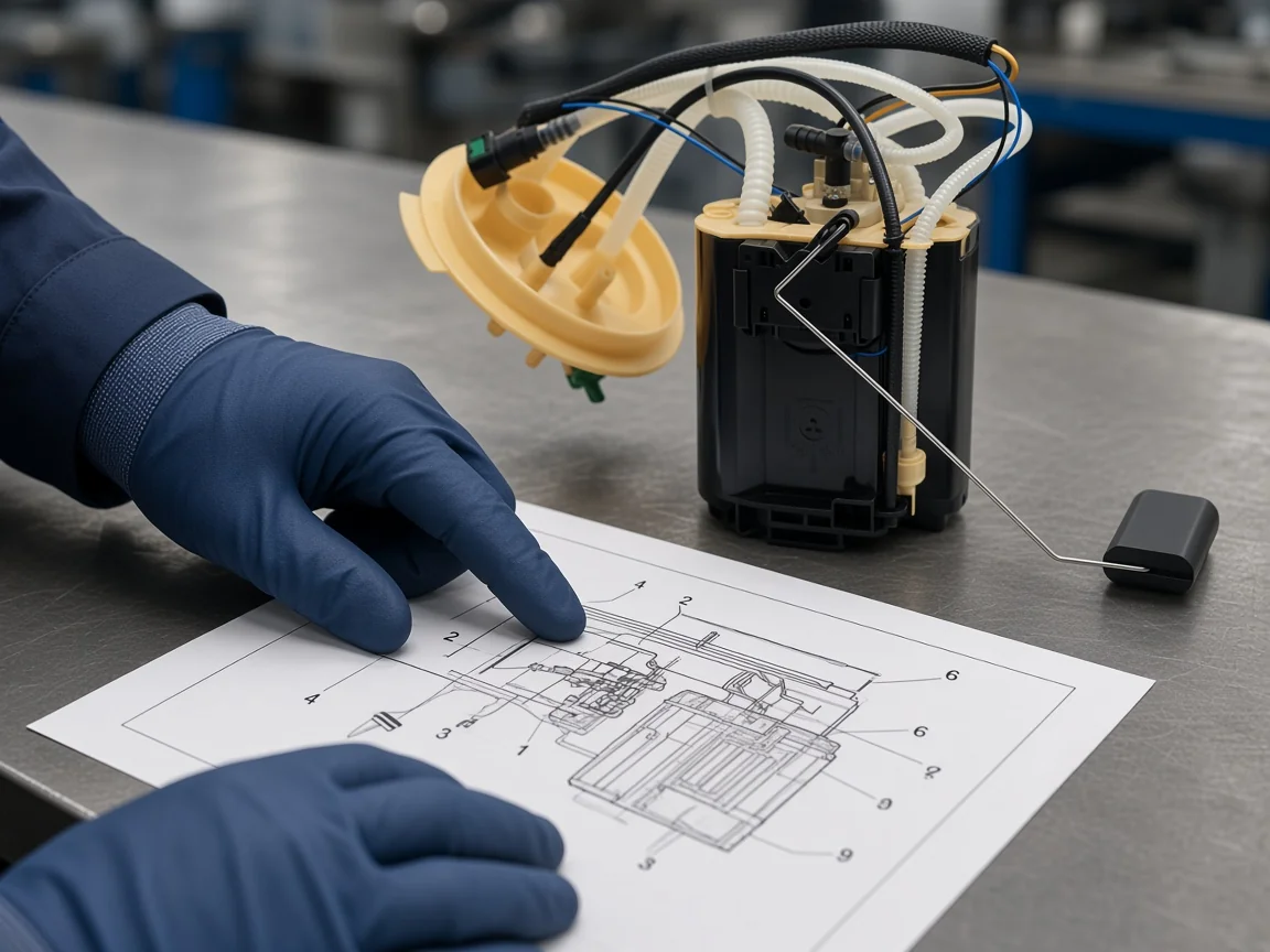
Important: High-pressure diesel lines are injury hazards. Never loosen a high-pressure line with the engine running; treat any suspected injection injury as an emergency and follow the OEM procedure for your engine family — source: independent inline-pump architecture safety notes.
Two-stage valve notes on the DD15 sheet show why low-pressure numbers still matter: the valve stays closed below 3 bar relative to high-pressure-pump backflow, the lubrication path is fully open at 3.5 bar, and overrun routing opens above 4.7 bar. Those thresholds explain why a flow diagram spends ink on the low-pressure side even when readers came looking for the rail.
Mechanical diesel fuel pump diagrams: in-line vs distributor
In-line drawings show one element per cylinder; distributor drawings show one plunger serving every cylinder.
An in-line injection pump houses as many pumping elements as the engine has cylinders. Each plunger and barrel pair sits in a row, lifted by the pump camshaft, with quantity set by rack position and helical geometry.
Bosch PE technical figures label that geometry plainly: delivery-valve holder, barrel, inlet and spill ports, control helix, pump plunger, control sleeve, control rack, roller tappet, and cam. Pump-side maximum injection pressures in that PE instruction sit between 400 and 1,150 bar, and the size-series table lists 550, 750, 1100, 950, and 1300 bar depending on the pump family row.
A distributor / rotary injection pump takes the opposite packaging choice. One central pumping element builds pressure, then a distributor head routes fuel to each outlet in firing order. Bosch VE technical instruction describes that compact package as combining a fuel-supply pump, a high-pressure pump, a governor, and a timing device in one housing.
| Diagram cue | In-line mechanical | Distributor / rotary |
|---|---|---|
| Pumping elements | One plunger-and-barrel per cylinder | One central plunger for all cylinders |
| Quantity control you usually see | Control rack rotating plungers / sleeves | Control collar or electronic actuator on a shared plunger |
| Typical sheet focus | Row of elements, rack, delivery valves | Cam plate or rotor, distributor head, advance piston |
| Reader risk | Counting elements against cylinder count | Assuming every outlet has its own pumping barrel |
From the field: On mechanical inline pumps, technicians describe a helical groove on the plunger and a rack that rotates it so the helix meets the spill port earlier or later—injection starts at the same crank position, but ends when that spill path opens.
That control rack / helix / spill port language is what a mechanical diesel fuel pump diagram is trying to show. If the sheet in your hand never shows a rack or a helix, you may already be looking at a different architecture.
How a common-rail diesel fuel injection pump diagram differs
The high-pressure pump feeds a shared rail; injectors open on command instead of taking a discrete pump pulse only.
Common rail direct injection stores fuel in a high-pressure accumulator that feeds solenoid or piezoelectric injectors. Encyclopedia summaries place typical common-rail pressure over 2,000 bar (200 MPa; 29,000 psi).
Third-generation common-rail systems are described with fuel pressures up to 2,500 bar (250 MPa; 36,000 psi). A separate fuel-injection overview cites third-generation piezoelectric common-rail diesels at fuel pressures up to 300 MPa or 44,000 psi. Keep those bands on the common-rail encyclopedia statements, not on a Freelander assembly photograph.
| Figure on the page | Typical meaning | Keep it on |
|---|---|---|
| Over 2,000 bar (200 MPa; 29,000 psi) | Typical common-rail operating class | Common-rail system diagrams |
| Up to 2,500 bar (250 MPa; 36,000 psi) | Third-generation common-rail band | Third-gen CR descriptions |
| Up to 300 MPa or 44,000 psi | Third-gen piezoelectric CR citation | That encyclopedia sentence only |
| 900 bar (13,053 psi) on a numbered flow | One engine family’s HP-pump callout | The DD15 Version Five sheet that prints it |
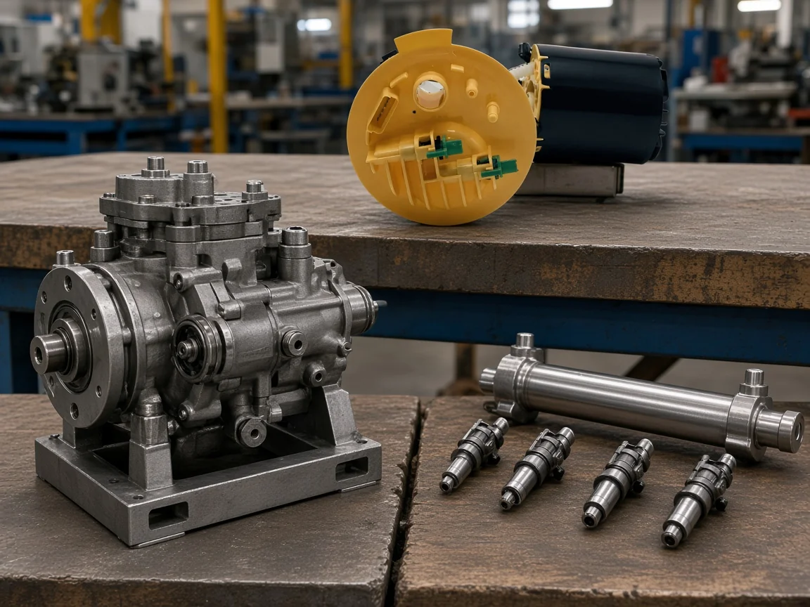
On a common-rail diesel fuel injection pump diagram, look for the lift / supply / low-pressure pump, the high-pressure supply pump, the high-pressure rail, rail sensors or relief valves, injectors, and return manifolds. The rail is the shared pressure store; the injectors are no longer waiting for a cam-timed pulse from a dedicated pumping element on every stroke.
Diesel fuel injection pump diagrams for older P-L-N systems still matter for fleets that keep mechanical pumps in service. The reading habit is the same: name the architecture first, then trust the callouts that belong to that architecture.
Exploded views, Isuzu pump-family sheets, and common reading mistakes
An aftermarket Isuzu/Zexel PFR exploded view is a pump-family parts map, not a redrawn vehicle OEM plate.
Parts indexes publish interactive diesel fuel injection pump diagrams for many pump families, including CAV DPA/DPC units, Bosch VE and CP-series pumps, and an Isuzu / Zexel PFR exploded view such as PFR1KX50/55/60. Those pages help you click a callout to a spare. They do not authorize inventing a missing Isuzu vehicle OEM drawing.
When readers ask for a cross-section that is not published, the honest answer is to stop. Community threads about hard-to-find high-pressure pump internals show how often people hit a blank wall looking for a clear illustration. Blank walls are not permission to fabricate plates.
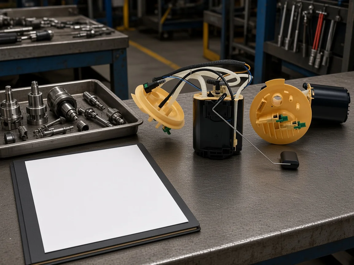
Three practical mistakes show up again and again:
- Treating an isuzu diesel fuel pump diagram from an aftermarket index as if it were the OEM plate for a specific truck VIN.
- Copying bar or micron numbers from one engine family’s flow sheet onto another family’s exploded view.
- Ordering a gasoline in-tank module because the photograph looked “close enough” to a diesel assembly.
Diesel fuel injection pump diagrams also show return lines for a reason. Overflow, rail relief, injector leak-off, and pump cooling paths keep pressure and temperature in range. Cutting a return “to simplify the hose map” is not a reading strategy; it is a different system.
Choose one Freelander 2 2.2 Diesel fuel pump assembly after the diagram
Open the assembly whose printed title names Land Rover Freelander 2 2.2 Diesel and the OE numbers on that page.
After you finish reading the diesel fuel pump diagram families, the next useful page is a live product whose printed fitment matches the vehicle you actually have. For this package that handoff is the fuel pump assembly (Freelander 2 2.2 Diesel) on the Land Rover Freelander 2 2.2 Diesel fuel pump assembly page.
That page prints suitability for Land Rover Freelander 2 2.2 Diesel and lists OE numbers including LR010434 and LR029279, with the title also carrying LR038602, LR005622, and LR010432. Fitment stops at that printed title and overview. It does not prove Bosch, FASS, AirDog, or Facet equivalence, and it is not a gasoline SKU.
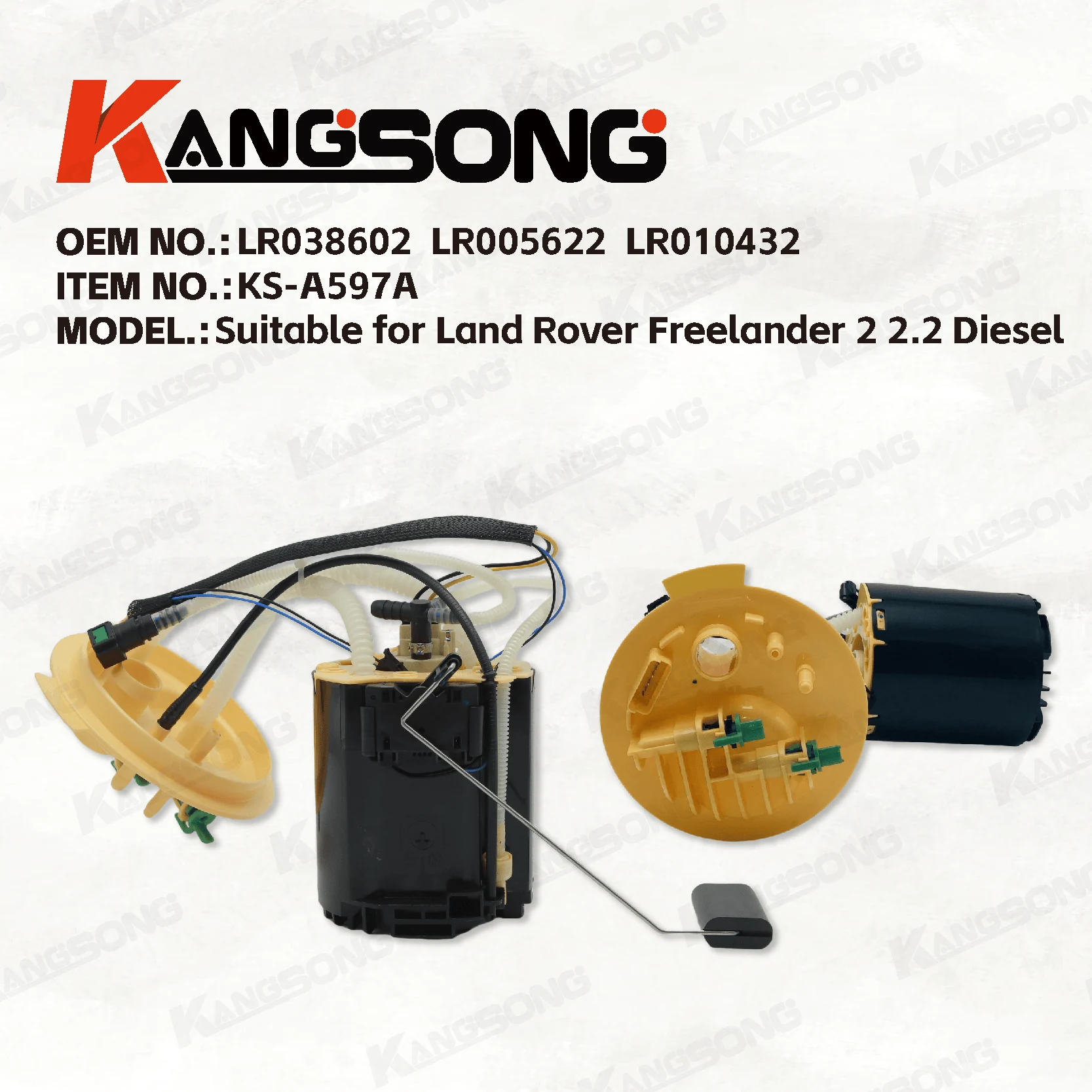
If the drawing in your hand names a different vehicle, engine, or OE set, leave this page and browse the catalog root at Kangsongpower Products for another printed match. Public /shop/ and /products/ paths are not usable navigation on this site.
FAQ
What does a diesel fuel pump diagram show?
It shows the labeled path from tank through filtration and the injection or supply pump to the injectors, including return routes when the system uses them.
How do you read callouts on a diesel fuel injection pump diagram?
Match the number on the picture to the same number on the parts or flow list, then keep every micron or bar figure on the engine family printed on that sheet.
How is a mechanical diesel fuel pump diagram different from a common-rail diagram?
Mechanical sheets emphasize cam-driven plungers, racks, helixes, and discrete high-pressure pulses. Common-rail sheets emphasize a shared high-pressure rail and electrically timed injectors.
What does an in-line diesel fuel injection pump diagram label that a distributor diagram does not?
In-line drawings show one plunger-and-barrel element per cylinder. Distributor drawings show one central plunger routing fuel through a distributor head.
Can I treat an isuzu diesel fuel pump diagram from a parts site as an OEM vehicle plate?
No. Aftermarket indexes may publish a Zexel Isuzu PFR exploded pump-family view for spare parts. That is not permission to invent or redraw an OEM vehicle plate.
Why do diesel fuel injection pump diagrams show return lines?
Return and overflow paths move excess fuel, cool components, and stabilize pressure after relief or injector leak-off. Removing them from the mental model breaks the circuit the sheet is describing.
What pressure numbers are safe to quote from a common-rail diagram article?
Quote encyclopedia typical bands such as over 2,000 bar (200 MPa; 29,000 psi) for common rail, and keep third-generation figures on third-generation wording. Do not stamp those bars onto an unrelated Freelander assembly photo.
How does a Freelander 2 2.2 Diesel fuel pump assembly page relate to these diagrams?
It is the scoped product handoff after diagram literacy: open it only when the printed Freelander 2 2.2 Diesel title and OE list match the vehicle you are buying for.
References
- Pump-Line-Nozzle Injection System (DieselNet). Independent technical overview of in-line, unit-pump, and distributor P-L-N architectures.
- DD15 Section 1 The Fuel System (Detroit manuals mirror). Numbered Version Five flow description with filter micron and rail-side bar callouts.
- Injection pump diagram thread (The Diesel Stop). Community request for an injection-pump diagram and replies about an inlet filter screen.