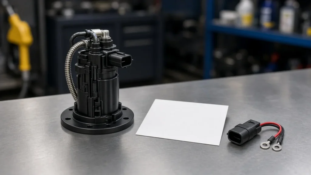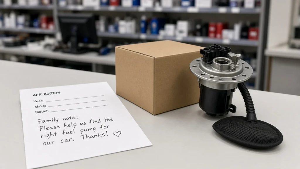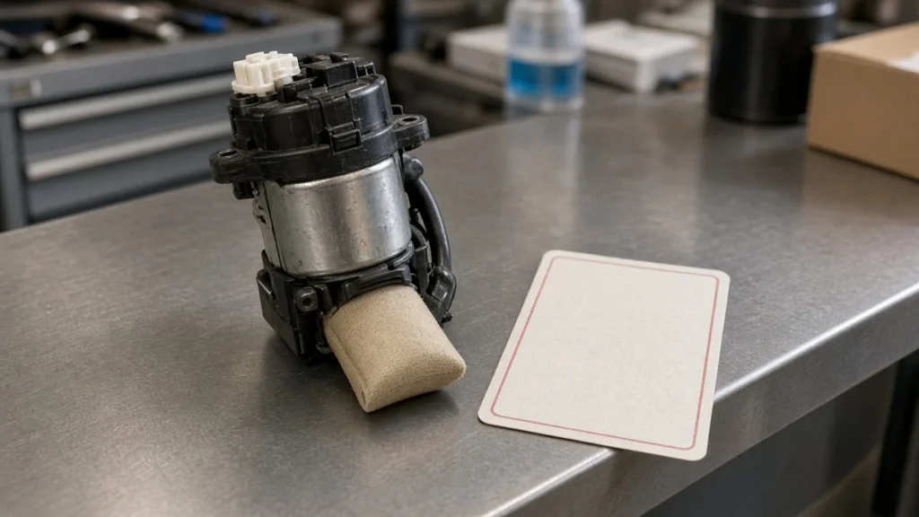
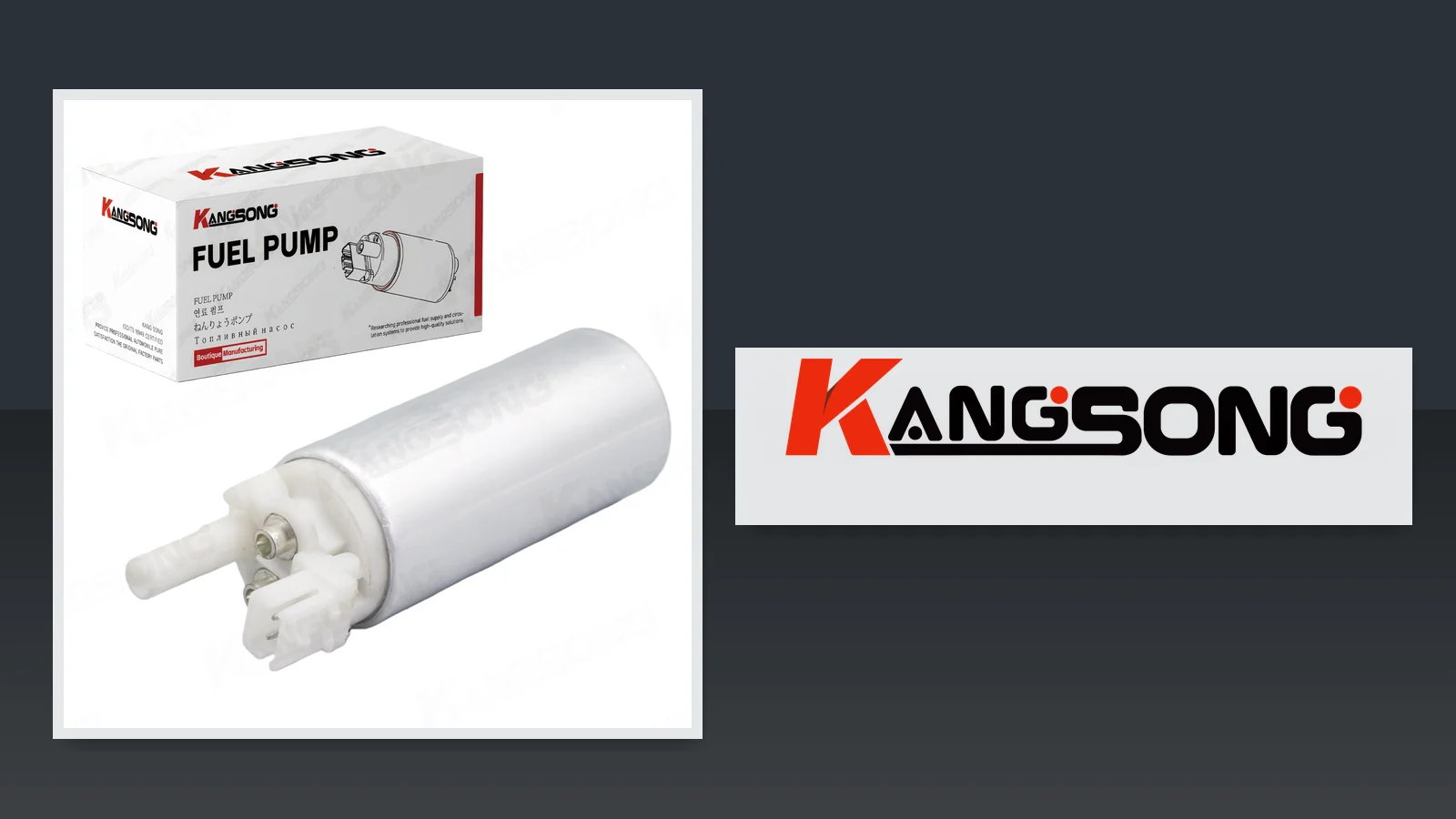
An inline fuel pump diagram is a labeled-port legend: it shows how fuel and power meet a line-mounted pump so you can match IN/OUT, strainer, extra ports, terminals, and orientation before you source a kit. Use it as a reading job, not as a stand-in for what an inline fuel pump is. The walk below is the capture list for RFQ, then a printed-fitment electric kit only when the legend matches.
How to Read an Inline Fuel Pump Diagram Legend
Treat the drawing as labeled ports on a line-mounted supply pump, not a plunger injection cutaway.
An in-line electric pump sits in the fuel line. Motorservice’s block diagrams put that pump between tank and engine, unlike an in-tank fuel pump module that lives in the tank with a sender.
A diesel inline fuel injection pump drawing is a different family. Those cutaways name plunger, barrel, spill hole, and delivery valve because the pump meters high-pressure fuel to injectors. Do not send that photo as proof for an electric supply-pump kit.
| Label you will see | What it marks | What to write on the RFQ |
|---|---|---|
| IN / inlet / suction | Tank or pre-filter hose | Fuel pump inlet and outlet sizes and thread or quick-connect family |
| OUT / outlet / discharge | Engine, carburetor, rail, or downstream filter | Same, plus hose ID if the sheet calls it out |
| Arrow / FLOW | Tank toward engine | Confirm arrow direction against the physical housing |
| Filter / strainer / sock | Inlet-side debris control | Inlet strainer present: yes/no; separate canister or integrated |
| Return / bypass / unused | Extra fuel path | Third port function, not assumed as a second inlet |
| + / − / 2-pin | Motor power | Pin count and polarity marks, not hose direction |
| Angle / height / terminal-down note | How the body should sit | Copy the sheet’s pose; do not import another brand’s pose |
If the file shows cam rings and helix grooves, park it. Diesel inline fuel pump selection is a sister job.
IN and OUT Ports and the Flow Arrow
IN is the tank or pre-filter side; OUT is the engine side; follow a stamped arrow when one exists.
The inlet port takes fuel from the tank hose or from a pre-filter. The outlet port sends fuel toward the carburetor, fuel rail, or the next filter. Retailer install language matches that split: tank hose on inlet, engine hose on outlet.
A flow arrow, when it is cast or printed, points from tank toward engine. Reverse the housing and you quote a pump that will starve or leak at the first prime.
Missing arrows are common on used or relabeled units. On Thirdgen, one owner asked which side was in or out because the electrical posts sat on one end and no arrow remained.
Another reply said that particular Walbro put terminals on the outlet end. Treat that as one housing, not a universal rule.
When the stamp is gone, stay with the drawing: IN to tank, OUT to engine. Do not invent a blow-through test from small-engine pulse pumps and apply it to an EFI electric unit.
Strainer and Pre-Filter Marks on the Inlet
The strainer or kit pre-filter belongs on the inlet story.
An inline fuel pump strainer is the mesh, sock, or small canister that stops rust and varnish before the pumping element. Wikipedia’s electric-pump assemblies often package a strainer on the inlet side. AA1Car describes fuel drawn through an inlet tube and mesh sock, then pushed out past a check valve.
Kit sheets often thread a small filter into the pump inlet. Derale’s 72000-family drawing is explicit: the threaded side of the inline filter is the filter outlet, and those threads screw into the inlet side of the pump. FAST’s in-line kit notes an integrated pre-filter on the pump itself.

From the field: Missing arrows still show up on used housings. On AskMechanics, techs still kill pumps with a choked inlet screen or a regulator that will not open the return, so the motor dead-heads. Read strainer and return marks on the diagram before you order another unit.
A clogged inlet screen looks like a “weak pump” on the counter. Capture whether the drawing shows a separate pre-filter, an integrated strainer, or only a clean IN boss.
Bypass, Return, and Extra Ports That Are Not Fuel Feed
A third fitting may be return, bypass, vapor, or pulse — read the label.
On return-style EFI, AA1Car has the rail regulator send unused fuel back to the tank. That fuel pump return line is not a second inlet. Plug it as IN and you flood the suction side or dead-head the outlet.
SAE J2044 covers quick-connect couplings for supply, return, and vapor/emission lines on automotive and light-truck fuel systems. The recommended practice lists operating pressure up to 500 kPa (5 bar, 72 psig), vacuum down to −50 kPa (−0.5 bar, −7.2 psi), and −40 °C (−40 °F) to 115 °C (239 °F). Two couplings that look alike can still be different circuits.
| Extra port on the drawing | Likely function | Do not treat it as |
|---|---|---|
| RETURN / BYPASS | Excess fuel to tank | A second IN |
| Vapor / EVAP (J2044 family) | Vapor/emission connection | Liquid feed |
| Pulse / vacuum (mechanical) | Crankcase pulse for a diaphragm pump | Electric pump inlet |
| Unused / plugged | Capped boss on that body | A required hose |
Small-engine threads warn that a third hose can be crankcase pulse, not fuel. If your RFQ photo is a pulse pump, say so. An electric inline supply drawing should not grow a mystery third fuel hose without a printed RETURN or BYPASS callout.
Electrical Terminals on the Same Drawing
+/− or 2-pin marks are motor power, not fuel direction.
Electrical terminals on the same sheet tell you how the motor is fed. Willand-style legends show positive and negative points. FAST’s in-line instructions mark polarity on threaded wiring studs and want the ground ring on clean bare metal.

A 2-pin connector on a printed kit is evidence of motor power, not proof of hose clocking. Color myths lose to the stamp on the housing. Full relay, fuse, and ground procedure lives on the 12-volt wiring sister; this page only asks you to copy the terminal marks into the RFQ.
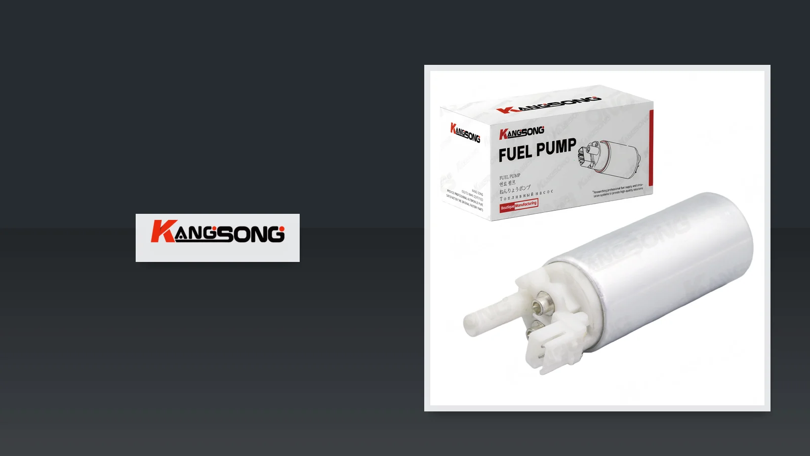
Kangsong’s printed electric kit example lists a 2-pin main connector and DC 12V on the product page. Use those fields after the drawing’s polarity marks match the physical plug.
Mounting Orientation Cues the Diagram Is Telling You
Copy the sheet’s angle, height, or terminal note; do not import another brand’s pose.
Mounting orientation is a drawing instruction. Derale’s 72000-family sheet recommends a 30–45 degree mount with the outlet higher than the inlet so vapor can pass. Aeroflow’s low-pressure inline sheet says not to sit more than 12 inches (300 mm) above the tank bottom and wants the outlet at least 45 degrees above horizontal.
A Carter-style Summit sheet takes a different pose: never more than 24 inches above the bottom of the tank, and mount with the electric terminal pointing down. FAST wants the pump below the lowest tank level so it can prime when the tank is low. AutoZone’s electric-pump write-up keeps the unit close to the tank, typically within two to three feet and below fuel level.
Those numbers are sheet-specific. If your customer drawing shows terminal-down, do not “correct” it to outlet-high because another PDF said so. Write the pose you actually have.
What to Capture From the Diagram Before You Source a Pump
Capture ports, strainer, extras, terminals, orientation, then printed OE.
- Drawing family: electric in-line supply versus diesel injection-pump internals versus in-tank module.
- IN and OUT labels, thread or quick-connect size, and flow arrow.
- Strainer or pre-filter: separate, integrated, or none shown.
- Extra ports: return, bypass, vapor, pulse, or plugged.
- Electrical marks: +/−, stud vs 2-pin, ground note.
- Orientation: angle, height above tank, terminal-down or outlet-high.
- Printed vehicle/OE window on the SKU you will actually buy.
Hand that list to sourcing. Do not pad it with MOQ, certificates, or a brand ranking the site cannot support. For manufacturing programs, the OEM fuel pump manufacturer landing is the process page, not a substitute for the port list.
A diesel fuel pump diagram sister owns diesel drawing families. Keep this capture list on electric line-mounted supply pumps.
Choose Electric Fuel Pump Kits After the Port Legend Checks Out
After the legend matches, open a printed-fitment electric kit — not a random assembly.
Browse Kangsong electric gasoline fuel pump kit listings from the catalog root when you need navigation. For a worked example after IN/OUT, strainer, extras, terminals, and orientation check out, use the electric gasoline fuel pump with installation kit for 1987–1995 C/K.
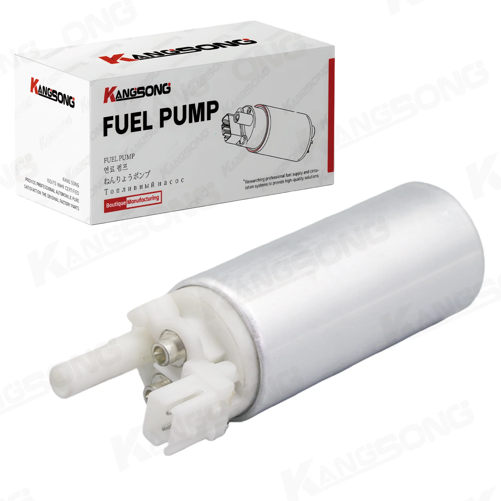
That PDP title scopes 1987–1995 C/K 1500/2500/3500 pickup trucks and OE 25168719 / E3902. The same page lists KS-360501, a 2-pin connector, DC 12V, and 43.3–49.5 Gph. It is not a universal inline pump and not a Hyundai/Kia Sonata assembly default.
Skip this kit when the drawing is a diesel injection pump, when the OE window is not that printed C/K set, or when the reader still needs an in-tank module exploded view. OEM buyers who already have a port list can continue on the manufacturer landing.
FAQ
How do I tell inlet from outlet if the pump has no arrows?
Use the diagram first: IN is tank or pre-filter, OUT is engine. A missing arrow is a common field complaint; one brand’s “terminals on the outlet” note is not a standard. Do not guess from hose color.
Does the strainer or pre-filter belong on the inlet or the outlet?
On the inlet. Kit drawings often thread the small filter into the pump inlet; some pumps integrate a pre-filter there. An outlet-side filter is a different part downstream of discharge.
Is a third hose on the drawing a return, a bypass, or a pulse line?
Read the printed word. Return or bypass sends unused fuel to the tank.
A pulse hose on a mechanical pump is crankcase air, not fuel. SAE J2044 also separates supply, return, and vapor quick-connects.
Which electrical marks on the diagram are positive and negative?
The +/− stamps or the 2-pin legend on the motor. They do not tell you which fuel boss is IN. Copy polarity from the drawing, then keep relay and fuse work on the wiring sister.
Do outlet-high mounting angles apply to every inline pump drawing?
No. One sheet says 30–45 degrees with outlet high; another says terminal pointing down; others cap height at 12 inches or 24 inches above the tank bottom. Quote the sheet you were given.
Can I use a diesel inline injection-pump diagram to source an electric inline pump?
No. A plunger-and-barrel injection-pump cutaway is not an electric line-mounted supply-pump legend. Send the wrong family and the kit will not match the ports.
What should I send with an RFQ after I read the diagram?
The seven-item capture list: family, IN/OUT, strainer, extra ports, terminals, orientation, and printed OE/vehicle. Then open a matching printed kit or the OEM landing — not a generic enquiry form.
References
- Fuel pump — Wikipedia (electric vs mechanical families; strainer on assemblies).
- Electric Fuel Pumps: How They Work, Why They Fail — AA1Car (inlet sock, return to tank, outside-tank pumps).
- SAE J2044 recommended practice — supply, return, and vapor quick-connects.
- Electric fuel pumps keep dying — r/AskMechanics (inlet choke and return dead-head language).