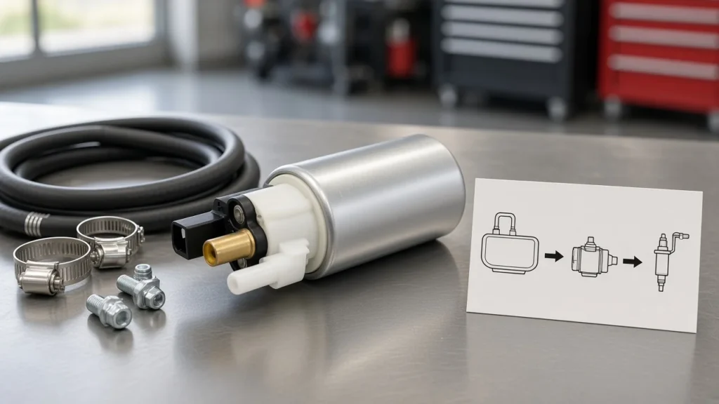
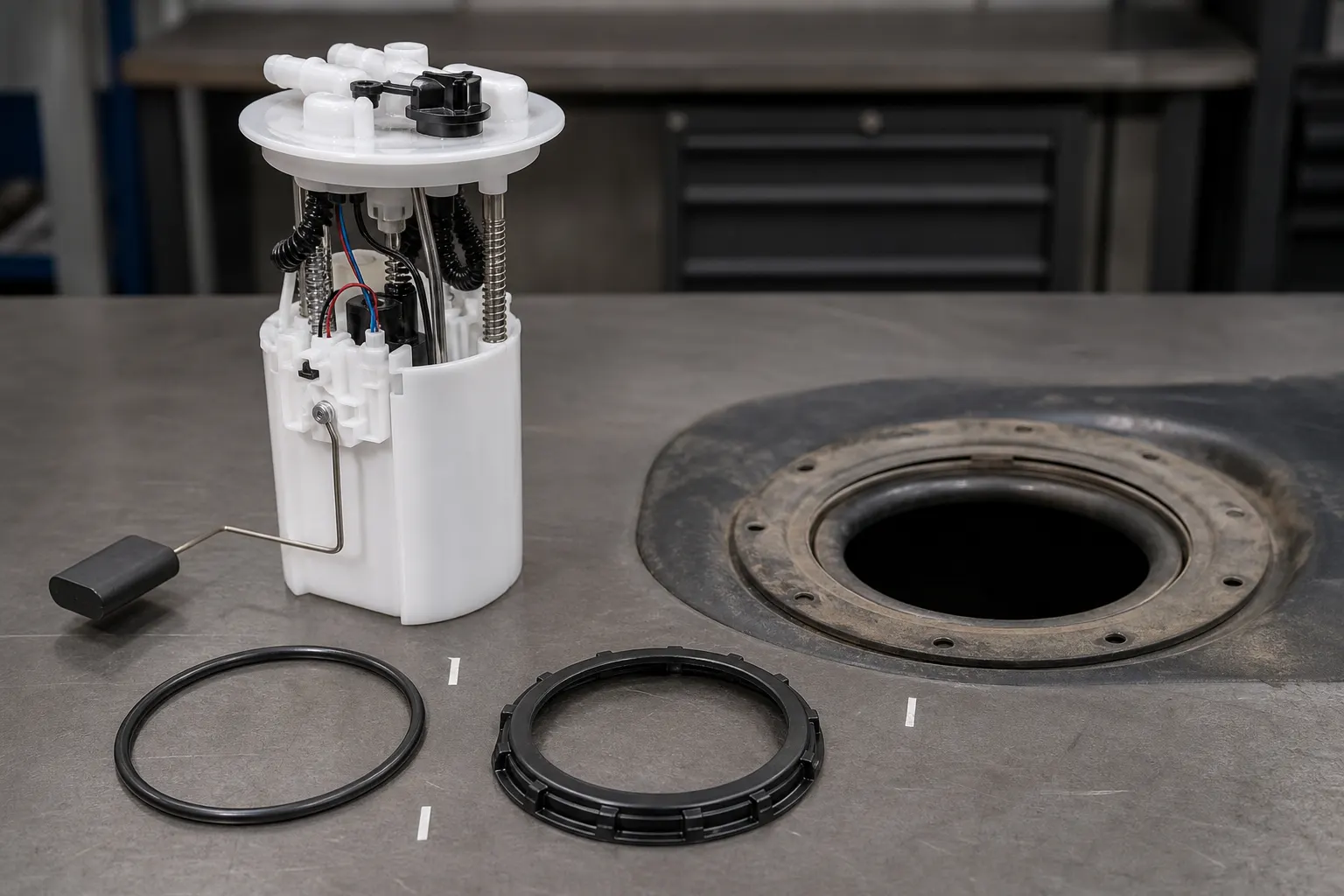
How to install fuel pump assembly safely starts with pressure relief and power isolation, then moves through part matching, a fresh flange seal, correct float clocking, secure fuel and electrical connections, priming, and a final leak inspection. That order applies whether the tank unit is reached through an access hatch or after the tank is lowered, while the vehicle service procedure still controls the exact access method and fastener specifications.
A complete fuel pump module installation is more than lowering a new unit into the tank. The pump, flange, tank seal, fuel-level sender, float arm, fuel lines, and harness have to return as one working system before the opening is covered.
What Installing a Fuel Pump Assembly Actually Includes
Start by confirming that the box contains a complete tank unit and that its flange, ports, connector, sender, and float arrangement match the unit coming out. Some service jobs replace an entire fuel pump assembly, while others replace only the electric pump inside the original carrier.
An in-tank fuel pump assembly commonly brings the pump, reservoir or carrier, tank-top flange, electrical pass-through, and fuel level float / sender together. In plain terms, the assembly is the complete unit at the tank opening; a pump-only insert is one component inside that unit, and an in tank fuel pump install should not confuse those scopes.
Lay the old and new parts side by side before the tank opening is exposed. Compare the following physical points:
- Flange shape and locating tabs
- Supply and return-port count, position, and fitting style
- Electrical connector body and terminal layout
- Module height and reservoir shape
- Float-arm direction and free travel
- Included tank seal, strainer, clips, and retainers
This comparison catches a parts problem while the old module still provides a reliable visual reference. It also keeps the question “how to replace fuel pump assembly” separate from a pump-only rebuild that may require transferring the sender, wiring, hoses, or carrier hardware.
Shop shorthand can make the packing list sound less clear than it is. “Tank unit,” “in-tank module,” and “fuel pump module” often describe the complete assembly, while “pump motor” or “insert” usually points to the electric pump alone; confirm the actual contents instead of relying on the label.
Safety First: Depressurize and Isolate Power
Relieve residual fuel pressure, isolate pump power, disconnect the battery negative, and remove ignition sources before opening a line or tank flange. An engine that is switched off can still leave pressurized fuel in the delivery path.
Depressurization commonly starts by disabling the fuel pump relay / fuse and running or cranking the engine as directed until pressure is bled. Open the fuel cap as the service information specifies, keep the work area ventilated, and have the correct fuel-rated fire extinguisher within reach.
Important: Never treat a silent engine as proof that the fuel path is safe to open. Fuel-system instructions warn that pressure can remain after shutdown, so complete the vehicle-approved pressure-relief procedure, disconnect battery negative, and keep sparks or hot work away before the flange is disturbed (NHTSA-hosted service notice).
Drain and transfer fuel only with approved equipment when tank lowering makes that necessary. A lighter tank is easier to support, but the main safety reason is controlled handling of fuel and vapor rather than convenience.
Keep absorbent material ready for the small amount of fuel that may remain in opened lines. Cap or cover disconnected lines promptly so dirt cannot enter and vapor is not allowed to spread across the bay.
Plan Access Before Removal: Hatch or Drop-Tank
Confirm the access path before quoting bay time or removing interior trim: some vehicles provide a service hatch, while others require the tank to be supported and lowered. Access hatch vs drop tank is a vehicle design decision, not a choice the installer can make from a generic article.
A hatch may sit under a rear seat, load floor, or trunk panel. A drop-tank job adds fuel transfer, filler-neck, vent, strap, shield, and support work, so the repair information for the application must define that sequence.
Before any retaining hardware moves, vacuum or wipe the area around the tank opening. Dirt left on the top of the tank can fall directly into the fuel when the module clears the flange.
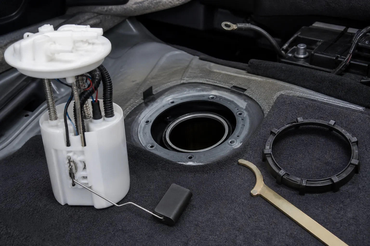
Use the exposed old module as an orientation record. Mark or photograph the direction of the outlet, electrical connector, indexing arrow, and float path before disconnecting anything, because those references become hard to reconstruct once the unit is on the bench.
Quick-disconnect fuel lines need the release tool and handling method specified for their collars. Pulling on a locked plastic fitting can damage the line or retainer, so release the lock, support the connector body, and close the open end against contamination.
| Pre-install gate | Ready to proceed | Stop and correct |
|---|---|---|
| Replacement scope | Complete assembly or pump-only job is confirmed | Box contents do not match the planned labor |
| Safety state | Pressure relieved, pump power isolated, battery negative disconnected | Fuel path may still be pressurized or an ignition source remains |
| Access plan | Hatch or tank-lowering method is known | Tank support, fuel transfer, or service information is missing |
| Flange area | Opening perimeter is clean before the ring moves | Loose dirt can enter the tank |
| Orientation record | Port, connector, index, and float direction are captured | Old unit may be removed without a clocking reference |
| Sealing parts | Correct new O-ring or gasket is ready | Old packing is the only available seal |
Seat a New Seal and Lock the Retaining Ring
Install the replacement module on a new, correctly seated tank seal, then bring the retaining hardware into full engagement without using force to hide misalignment. A reused or rolled seal can let liquid fuel or vapor escape even when the module looks level.
Remove the old tank seal / O-ring / packing and clean its groove and the mating surface. Check for debris, corrosion, damaged tabs, or a distorted lock-ring path before the new seal goes into place.
Set the fresh O-ring flat in its intended groove. If the service procedure allows a lubricant, use only the specified fuel-compatible product and amount; a lubricant is not a repair for the wrong seal size or a damaged flange.
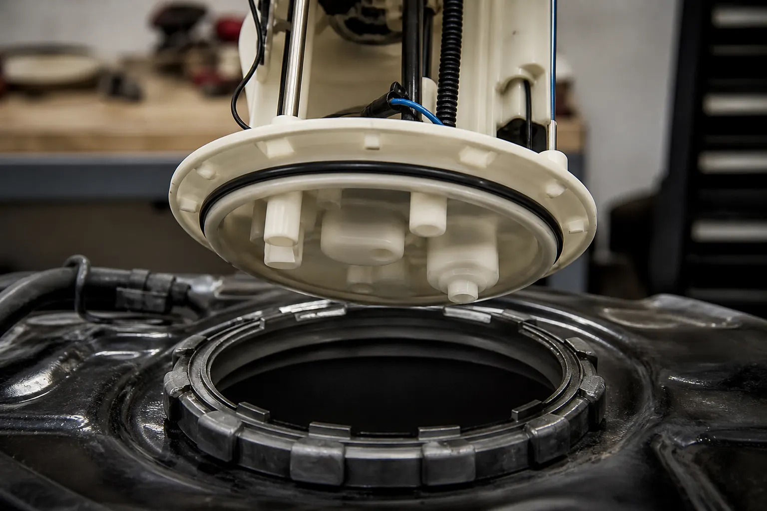
Lower the module evenly enough to keep the seal from rolling out of its seat. A lock ring / retaining ring should start square to its tabs, while a bolted flange should settle evenly in the sequence and torque stated by the vehicle manufacturer.
From the field: Installers often describe a new aftermarket O-ring as stiffer than the removed part and report that it pushes the module upward while the ring is started. When the ring fights back, recheck seal identity, groove seating, flange level, and tab alignment before adding downward pressure or using the proper sender-lock tool (AstroSafari lock-ring discussion).
Do not use a steel screwdriver where a spark could be produced at an open tank. A designated lock-ring wrench or an approved non-sparking method gives better control and reduces damage to the ring ears.
Fuel odor after replacement deserves attention at this stage, not a scented-cleaner explanation. Wetness or vapor at the module flange points first to the seal, ring engagement, mating surface, or line connection until inspection shows otherwise.
Clock the Module and Protect Float Travel
Align the new module with the tank indexing marks and guide the float through the opening without bending its arm. Correct clocking keeps the ports in their intended direction and gives the fuel-level sender room to move.
The float is the buoyant part that drives the sender used by the fuel gauge. If its arm contacts the tank wall, a baffle, or an internal hose, the gauge can stick or report the wrong level even though the pump itself runs.
Angle the assembly only as much as needed to clear the opening and internal hardware. Do not use the float arm as a handle, and do not bend it to make a mismatched module fit.
Indexing arrows, molded tabs, and the old unit’s outlet direction provide the clocking reference. Match those references before the seal is compressed, because rotating a seated module can disturb the O-ring.
Check that internal hoses and wiring lie inside the carrier as intended. A loose path can enter the float’s sweep or become pinched between the flange and tank.
The final visual check should show a level flange, aligned marks, clear ports, and a float that entered without impact. On applications where the float can be observed or moved before final seating, confirm its travel rather than assuming clearance from the flange position alone.
Reconnect Fuel Lines and the Electrical Harness
Engage every fuel-line retainer and the electrical harness latch fully before restoring the relay, fuse, or battery connection. A module can be mechanically secure yet still fail to prime because the power plug is loose, or leak because a quick connector stopped short of its lock.
Inspect the male and female sides of each fuel fitting for dirt, damaged O-rings, cracked collars, or bent retainers. Push the connection straight until its normal lock is felt or heard, then perform the application-approved pull check without yanking the line.
Treat the electrical connector as a sealed interface. Look for bent terminals, heat discoloration, corrosion, broken secondary locks, and a damaged perimeter seal before the plug is seated.
For a detailed release-tab and connector-removal procedure, use the sister resource on how to disconnect a fuel pump electrical connector. The assembly job needs a clean, fully latched reconnect; it does not need the connector deep-dive repeated here.
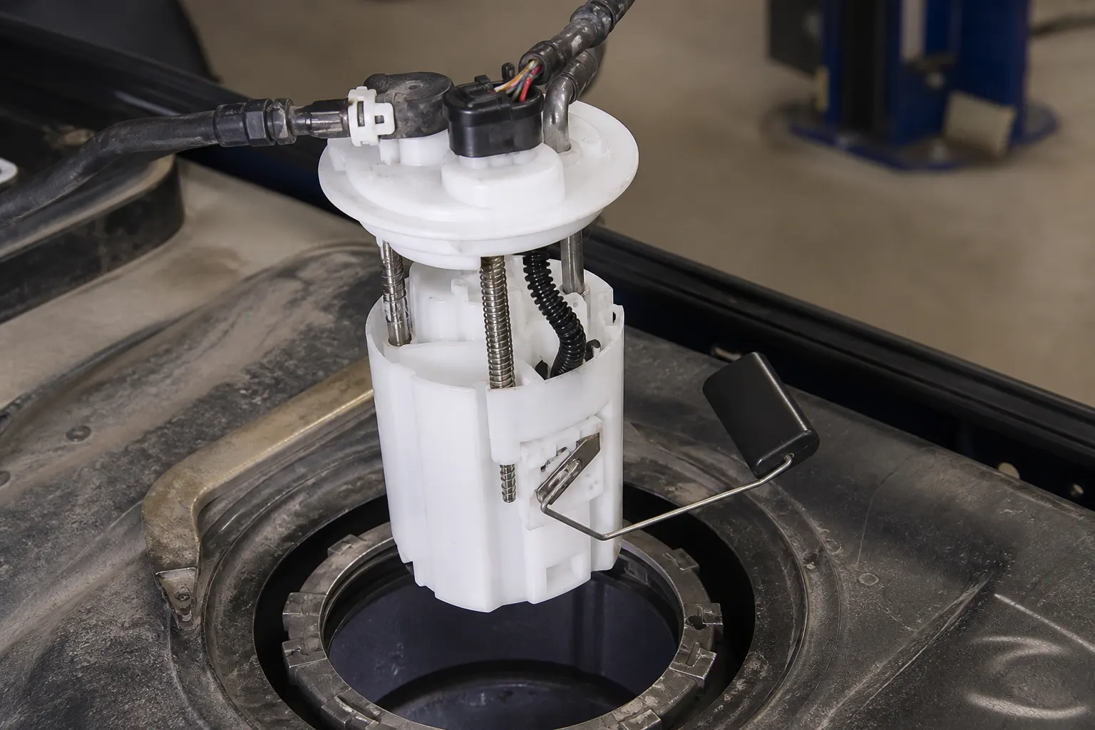
Route the harness and lines back through their original clips so they do not rub, kink, or load the module flange. Restore shields, straps, access covers, and interior panels only after the first prime and leak inspection leave the opened joints dry.
Reinstall the fuel pump relay or fuse and reconnect the battery in the order given by the repair information. Keep tools and absorbent material clear before power returns to the circuit.
Prime, Start, and Check for Leaks
Prime the opened fuel path before extended cranking, then inspect the tank flange and every disturbed line connection for wet fuel or vapor odor. The job is not ready to close until the module primes, the engine runs as expected, and the opened interfaces stay dry.
Use the vehicle-approved key-on sequence to command the pump and listen for its brief operating sound. Avoid inventing a universal cycle count, because control strategies and pressure-building instructions differ by application.
Watch the module flange during and after prime. A bead of wet fuel, a fresh odor, or a seal that lifts with pressure means power should be switched off and the connection corrected before the access cover is installed.
| Post-install result | What it suggests | Next action |
|---|---|---|
| Pump primes and opened joints stay dry | Electrical and sealing gates have passed the first check | Start the engine and repeat the visual inspection |
| No prime sound | Power, ground, relay, fuse, or connector may be incomplete | Isolate power and inspect the electrical path |
| Wetness at flange | Seal seating, ring engagement, or mating surface is wrong | Stop, depressurize, and reopen the flange |
| Wetness at a line | Quick connector, retainer, or fitting seal is not secure | Stop, depressurize, and service the connection |
| Gauge reading is implausible | Float travel, clocking, sender, or connector needs inspection | Check orientation and electrical continuity |
| Fuel odor remains with no visible wetness | Vapor sealing still needs a careful flange and line review | Do not install the final cover until the source is found |
Once the first inspection passes, start the engine and look again under operating conditions. Recheck the top of the module, supply and return fittings, nearby hoses, and any tank connections opened for access.
Confirm that the fuel gauge responds plausibly to the known tank level. If the engine runs but the gauge is stuck, return to float clearance, sender connection, and clocking rather than blaming the new pump motor.
Post-install delivery complaints may lead into a separate diagnostic tree. The in-tank fuel pump symptoms resource covers noise and delivery signs, while what size electric fuel pump do I need handles flow selection rather than installation order.
Choose Fitment-First Fuel Pump Assemblies After Pre-Checks
Use the Kangsong products catalog to browse application-scoped assemblies after the vehicle, engine, OE reference, connector, flange, and sender configuration are known. Fitment comes before price or visual similarity because two in-tank modules can look close while their height, ports, resistance range, or clocking differs.
A Kangsong fuel pump assembly is an automotive electric fuel-injection tank unit offered for application-based sourcing. The products-root catalog is the appropriate next path for a shop or counter that has completed the fitment and installation pre-checks.
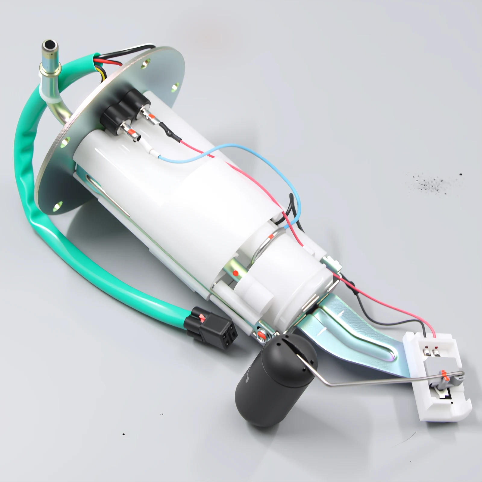
Carry the vehicle identity and OE reference from the removed unit into the catalog search. Then compare the connector, top flange, outlet direction, module depth, float geometry, and included sealing hardware before releasing the order.
If the open question is whether to use an external or submerged layout, read external fuel pump vs internal. A Holley-specific retrofit question belongs in the Holley Sniper in-tank fuel pump install pre-check instead of being folded into a general replacement order.
FAQ
How do you install a fuel pump assembly safely?
Relieve fuel pressure, isolate pump power, disconnect battery negative, clean the opening, and record the old module’s orientation before removal. Install the matched assembly on a new seal, protect float travel, secure the ring, reconnect lines and power, prime, and inspect for leaks before closing the access area.
How difficult is it to install a fuel pump?
Difficulty depends mainly on access and the equipment needed to handle the tank safely. A service hatch shortens the mechanical path, while a drop-tank repair adds fuel transfer, supports, straps, vents, and filler connections; both paths still demand the same seal, clocking, reconnect, and leak checks.
Do you have to prime a fuel pump after installation?
Yes, prime the opened delivery path according to the vehicle procedure before extended cranking. Priming also creates the first useful moment to inspect the flange and quick connections for leakage.
Does a fuel pump assembly come with a fuel pump?
A complete assembly normally includes the electric pump inside its carrier and may also include the reservoir, flange, sender, float, strainer, and some sealing hardware. Packing contents vary, so compare the new unit with the removed tank unit and confirm whether a fresh tank seal is supplied.
Can a fuel pump assembly be installed wrong?
Yes. A rolled or reused seal, incomplete lock-ring engagement, wrong clocking, bent float arm, loose quick connector, or unlatched harness can create a leak, inaccurate gauge reading, or no-prime condition.
How do you deal with a stuck fuel pump lock ring?
Stop adding force and check that the new O-ring is correct, flat in its groove, and not lifting the module unevenly. Confirm the flange is level and the ring starts square to its tabs, then use the proper lock-ring tool or approved non-sparking method.
Why does my car smell like fuel after module install?
Treat fuel odor as evidence that the sealing work needs inspection. Check the module O-ring, retaining-ring engagement, flange condition, quick-disconnect fittings, and any vent or filler connection disturbed during access; switch off power and depressurize before reopening a wet joint.
How is this different from disconnecting the electrical connector?
Release the application-specific lock without pulling on the wires, inspect terminals and seals, and push the clean connector together until its latch and secondary lock are secure. The fuel pump electrical connector guide covers release styles in more detail.
References
- NHTSA-hosted fuel pump module service notice — pressure warning, new O-ring, indexing, float clearance, and leak inspection.
- Charm.li fuel tank module replacement procedure — seal replacement, careful float clearance, priming, and leak inspection.
- AstroSafari lock-ring discussion — community experience with stiff O-rings and ring seating.
- S10 Forum retaining-ring discussion — community experience with O-ring resistance and sender-lock tools.
Draft Agent ID: KS-DRAFT-AGT-20260904-26
Humanizer audit: PASS
Second-pass note: Source-first and gate language was replaced with direct component and shop actions.
Second-pass note: Multi-decision paragraphs were split, and tables carry the stop/go checks.
Second-pass note: Connector, sizing, symptoms, architecture, and Sniper branches remain natural links instead of defensive disclaimers.
Second-pass note: No new fact, name, number, date, quote, citation, customer result, torque value, or first-person experience was added outside the approved research and brief.
Post-brief sync note: 2026-09-04 — H2 product recommendation title and shape contract synced to application/use-case brief after Brief Gate PASS.