A fuel pump assembly diagram is the numbered picture of one fuel module: the pump, the inlet screen, the level sender, and the fittings that leave the tank with them.
The useful habit is simple. Match the digit on the picture to the same digit on the parts list, then stop. A Chevrolet catalog row, a marine engine-group sheet, and a Volkswagen page with one printed year range are three different drawings.
What a fuel pump assembly diagram actually names
The drawing names the pieces that travel as one unit, not the pump motor by itself.
On many in-tank jobs the unit is the pump, the fuel strainer, and the fuel level sending unit on one housing. Fuel pump puts those three together in that order. The sender is there because the float lives in the same tank opening as the pump, not because the gauge and the pressure are the same job.
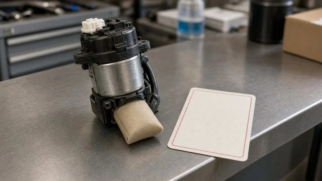
A module description aimed at drivers adds the pieces around that trio. The electric motor sits in a reservoir so fuel stays around the pickup in a corner.
A sock is the first screen. Many housings also carry a pressure regulator and a check valve, and the wires and fuel fittings pass through the top flange.
That map is laid out by ELMENS.
The same idea shows up on a model manual, with different numbers. On the Renault Symbol petrol system the figure marks 1 as the fuel filter, 2 as the tank, 3 as the filler pipe, 4 as the neck cover, and 5 as the fuel pump assembly.
The regulator on that car sits in the tank, inside the pump and level-sensor unit. The worked figure is on the Renault Symbol fuel-system page.
If the question is what the module is, before any callout, the companion page is what a fuel pump assembly is.
How numbered callouts line up with diagram fuel pump assembly parts
Match the digit on the picture to the same digit on the list before you order a hose or a seal.
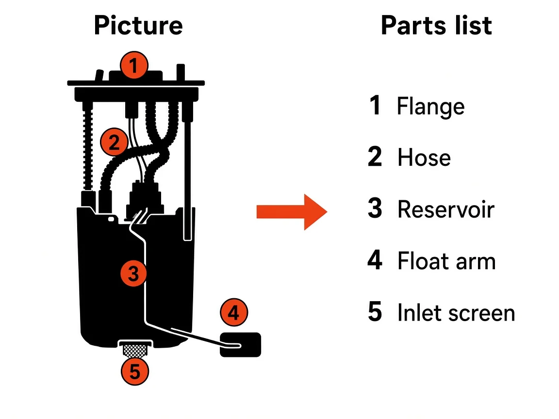
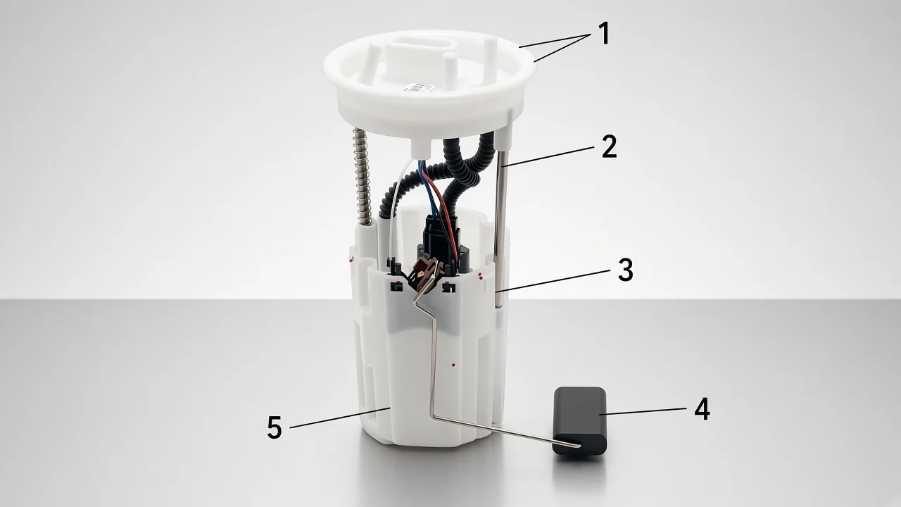
A callout is only a shared index. On the teaching picture above, 1 is the flange, 2 is the hose, 3 is the reservoir, 4 is the float arm, and 5 is the inlet screen.
The arrow is the whole method: the number on the left has to be the number on the right. A pretty legend that uses a different order is a different drawing.
Real sheets do the same thing with official hardware. The Symbol figure uses item 5 for the assembly and keeps the regulator inside that tank unit.
A community caption for a 1984-89 high-pressure EFI layout records a quieter kind of change: in February 1986 the frame-mounted filter was moved to sit between the pump and the engine. The caption is on SuperMotors.
If your car is in that span, the filter’s place on the sheet depends on the build month, not on a generic hose photo.
Readers who ask “where do the hoses go” are usually asking for this index, not for a color code. On a Z31 thread the useful reply did not invent a routing sketch.
It pointed the owner to the factory manual section for that car. Bring the sheet that names your pump, then read the numbers.
| Callout job | What you look at | What you ignore |
|---|---|---|
| Shared digit | The same number on the picture and the parts list | A legend that was written for a different model year |
| Inlet screen | The mesh on the pump inlet | The service fuel filter farther down the line |
| Level sender | Float arm and resistor on the housing | The assumption that a wrong gauge means the pump motor is dead |
| Regulator | The line that actually names a regulator | A photo of a cap on the old unit |
Where the strainer, sender, and regulator sit on one module
The fuel strainer sits on the inlet, the fuel level sending unit sits on the housing, and the pressure regulator is inside the module only when that system put it there.
The float is the sender. The pump motor is a separate piece.
That layout is why diagram fuel pump assembly parts has to show more than a motor silhouette.
One service description makes the list explicit for a single van. The 1999 Chevrolet Venture modular sender is the fuel sender strainer, the fuel pump strainer, a roll-over valve, the fuel level sensor, and a fuel tank pressure sensor, with a gerotor pump mounted on the sender.
The woven pump strainer both catches debris and wicks fuel toward the inlet. The page is the 1999 Venture fuel-supply description.
Those five names belong to that Venture module. They are a reading example for that Venture module only.
Access is part of the drawing even when the artist draws only the module. The unit drops through an opening in the top of the tank, and a lock ring closes that opening.
On some cars the opening is under the rear seat. On others the tank has to come down.
Apex Technation states both access paths, and it also notes that returnless systems carry the regulator in the module. If your sheet has no regulator line, leave the flange alone on that point.
The check valve is the small piece people skip. Where a module has one, it holds pressure in the line after shutdown so the next start does not need a long crank.
It is drawn as its own line when the sheet bothers to name it. It is not the sock, and it is not the gauge sender.
Pressure numbers on a general page are also tied to the pump type, not to the callout ink.
Mechanical pumps on carbureted engines are described at 10-15 psi (0.7-1.0 bar).
Older port-injection in-tank pumps are described at 40-60 psi (3-4 bar).
| Pump case | Where the drawing usually places it | Pressure band in the general description |
|---|---|---|
| Mechanical pump for a carburetor | On the engine | 10-15 psi (0.7-1.0 bar) |
| In-tank pump for older port injection | In the tank, often with the sender | 40-60 psi (3-4 bar) |
Direct injection adds a second, engine-mounted pump. The in-tank drawing still shows the lift module.
It does not become the high-pressure pump just because both parts move fuel. Keep the band next to the case that the encyclopedia entry actually describes.
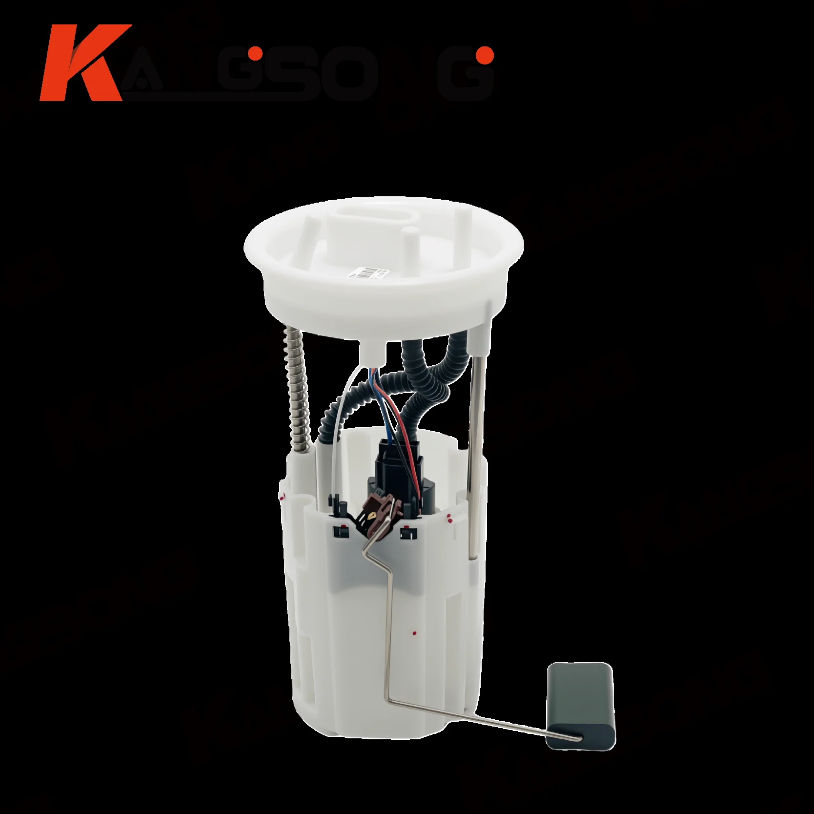
The photograph is one in-tank shape: a round flange, guide rods with a spring, corrugated hoses, a reservoir, and a float arm off the side. The pump motor is down in the reservoir.
What a chevy fuel pump assembly diagram is tied to
Tie a chevy fuel pump assembly diagram to one reference number and the vehicle rows printed beside it.
Catalog part 19369920 is marked as reference 10, and the page tells you to view the diagram for your vehicle. The rows listed with that part include 1996-1997 Chevrolet Tahoe, C1500, and C2500, plus the GMC counterparts on the same sheet.
Those rows stop at the trucks and SUVs printed on the sheet. A buyer with a 2004 sedan, or with a marine engine, is on a different sheet even if the search box said Chevrolet.
The Venture gerotor module from 1999 is a second Chevrolet example, not the same row. Its sender list includes a tank pressure sensor and a roll-over valve.
The catalog names that row a tank module kit with a level sensor. Same brand family, different drawings, different years.
The reference number is what the chevy fuel pump assembly diagram is for. Copying the picture onto the next truck is how the wrong strainer and the wrong lock show up in the box.
A Volkswagen OE number gets no coverage from that catalog row. If the sheet in your hand is reference 10 for those 1996-1997 trucks, stay on that sheet. If the number in your hand is a Touran OE, you are done with the Chevrolet page.
What a volvo penta fuel pump assembly diagram lists by position
A volvo penta fuel pump assembly diagram lists positions for one engine group, and those positions are not the in-tank car module.
On the fuel-pump-and-filter sheet for 5.0GLPBYC and 5.7GSPBYC, position 1 is fuel pump 3857985. The following lines name O-rings for the fuel line, a fitting, a fuel filter, a fuel-pump relay, a bracket, and the screws that hold that group.
The relay and the bracket are on the sheet because this pump is an external marine group, rather than a flange dropped through a car tank. There is no float arm in that position list, and there is no swirl-pot reservoir.
A diesel feed-pump sheet for the D1 and D2 series is a third layout again: a feed pump, a filter, banjo fittings, and hoses, with its own position numbers. Asking one picture to cover the gasoline sterndrive group and the small diesel feed pump is the same mistake as asking the Venture sender to cover the Touran.
The marine plate stays in the catalog. The position list is enough to see the lesson.
Read the engine models printed at the top of the sheet, then read the position numbers, then stop. A car-module photo with a float cannot stand in for position 1 on 5.0GLPBYC.
Hose and cap mistakes a drawing will not forgive
The drawing cares about port shape and the parts-list digit, not about the color of a shipping cap.
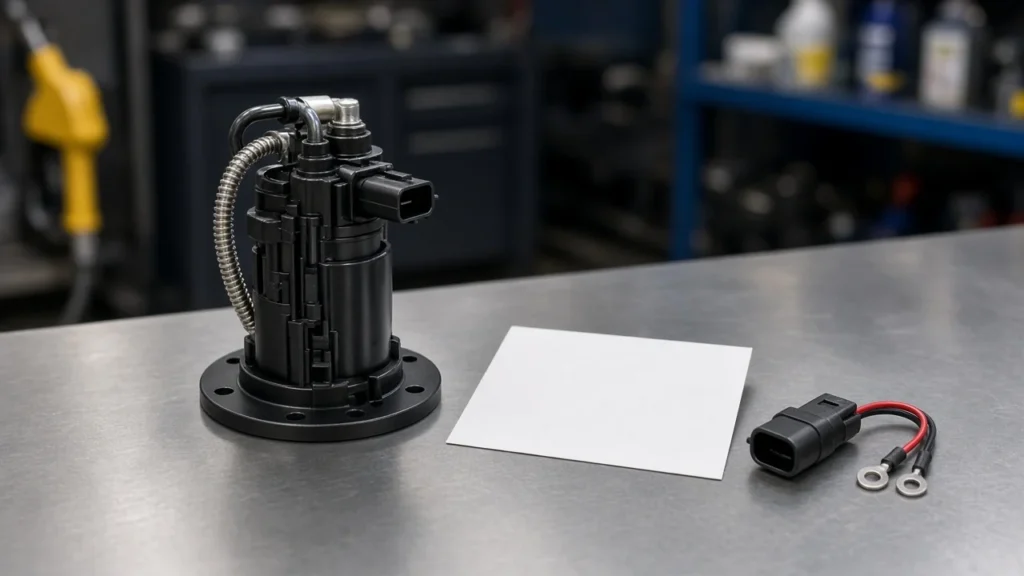
Important: Cap color is not the drawing – on a 1999 F-150 install the new pump’s blue cap did not meet the blue hose, and the reply that helped followed the tube with the single bend.
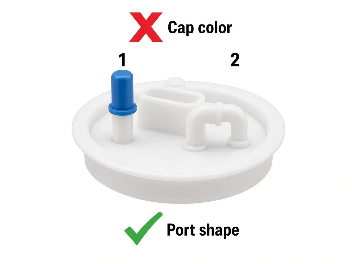
The teaching frame marks the failed cue and the useful cue. Cap color gets the X.
Port shape gets the check. One port is a straight outlet.
The other turns. Those shapes are what a hose diagram is for.
A new pump can ship with blue, black, or no cap at all, and the old car’s hoses can be stained a different color than the factory sketch.
The Z31 owner who asked for a picture of every hose was pointed at the factory manual section, not at a universal routing meme. Take photos before the lines come off, then put the factory numbers next to those photos.
A forum snapshot of someone else’s flange is a clue. It is not your callout list.
Two other mix-ups show up once the module is out. The inlet screen and the service fuel filter are different parts.
The screen lives on the pump inlet and catches the coarse debris. The filter, when the car still has a separate one, lives downstream and is the part with a service interval.
Replacing only the sock because the diagram showed a mesh will not refresh a plugged external filter. Replacing only the external filter will not clear a sock that has collapsed onto the inlet.
The sender is the other mix-up. A float that binds on the tank wall will lie to the gauge while the pump still runs.
When the pump quits, the gauge can stay honest and the engine goes quiet. Fuel pump assembly symptoms is the page for that split.
The diagram’s job is only to show that both parts can share one flange, so a gauge complaint and a no-start complaint are not automatic proof of the same failed piece.
Which printed Touran fitment to open after the drawing
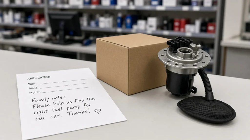
Open the assembly page whose printed line is OE 1TD919051 and 2004-2019 VW Touran, and leave every other drawing closed.

The photograph prints three identifiers in the frame: OEM number 1TD919051, item KS-A516A, and model Touran. The product page repeats them in words.
Compatible with Volkswagen. Product OE number 1TD919051.
Preview vehicle model: 2004-2019 VW Touran. That is the whole fitment claim the page will stand on.
The link is Fuel pump assembly 1TD919051 for 2004-2019 VW Touran.
Use that page when the number in your hand is 1TD919051 or the job is a Touran in those years and you still need the module with the flange, reservoir, and float. Skip that page when the picture in hand is Chevrolet reference 10, or when the words fuel pump appear on a Volvo Penta position list.
The float and the reservoir on this photo are the in-tank car pattern. They are not position 1 on the 5.0GLPBYC sheet, and they are not the 1996-1997 truck module.
If the OE number is different, stay in the catalog and read the next printed line instead of forcing this one. The category index is Kangsong products.
It is a map of pages. Fitment still comes from the printed number on each page.
The diagram habit still applies there: match the printed number, then open the page.
FAQ
What components are included in a fuel pump assembly?
Often the pump, the fuel strainer, and the fuel level sending unit, plus the flange, hoses, and a lock ring. Many in-tank housings add a reservoir, a pressure regulator, and a check valve. The sheet for your vehicle is the list that counts.
Why is the fuel level sending unit part of the fuel pump assembly?
The float has to sit in the fuel, and the pump already occupies the tank opening. Mounting the resistor on the same housing saves a second hole in the tank. The gauge circuit and the pump motor still do different work.
How do I find specific parts within the fuel pump and fuel level sensor assembly?
Read the position number on the picture, then find that same number on the parts list under the figure. On the Symbol manual the assembly itself is item 5. On a catalog row, the reference number next to the module is the same kind of index.
Is the inlet screen the same part as the service fuel filter?
No. The inlet screen, or sock, is the coarse mesh on the pump.
The service filter is a separate element downstream on cars that still have one. A diagram that draws both should give them two numbers.
Does a colored cap on a new pump decide the hose?
No. Caps are shipping covers, and their color can disagree with the hose color on the car. Follow the port shape and the single bend or straight outlet named on the sheet.
Can a single Chevrolet module number stand in for every Chevy?
No. Part 19369920, reference 10, is listed against specific 1996-1997 truck and SUV rows.
The 1999 Venture sender is a different module with a gerotor pump and a tank pressure sensor. Each sheet keeps its own rows.
Does a marine engine-group sheet use the same layout as an in-tank car module?
No. The 5.0GLPBYC and 5.7GSPBYC fuel-pump sheet lists an external pump, O-rings, a filter, a relay, and brackets.
An in-tank car module lists a flange, a reservoir, and a float. The words fuel pump appear on both, and the hardware does not match.
References
- Fuel pump. Encyclopedia entry on in-tank assemblies and the pressure bands for mechanical and port-injection pumps.
- Fuel pump and assembly: what is inside the module. Independent description of the reservoir, sock, regulator, check valve, and sender.
- 1999 Chevrolet Venture fuel supply component description. Service description of one modular sender and its gerotor pump.
- Renault Symbol 2 fuel system design. Numbered system figure and the in-tank regulator note.
- Fuel system overview. Lock ring, tank access, and returnless regulator placement.
- 1984-89 EFI high-pressure fuel pump assembly diagram. Community caption noting the February 1986 filter move.