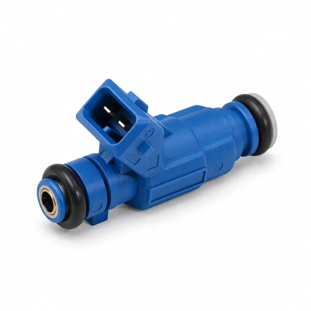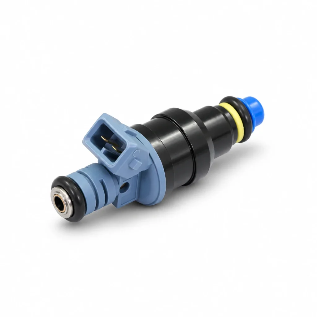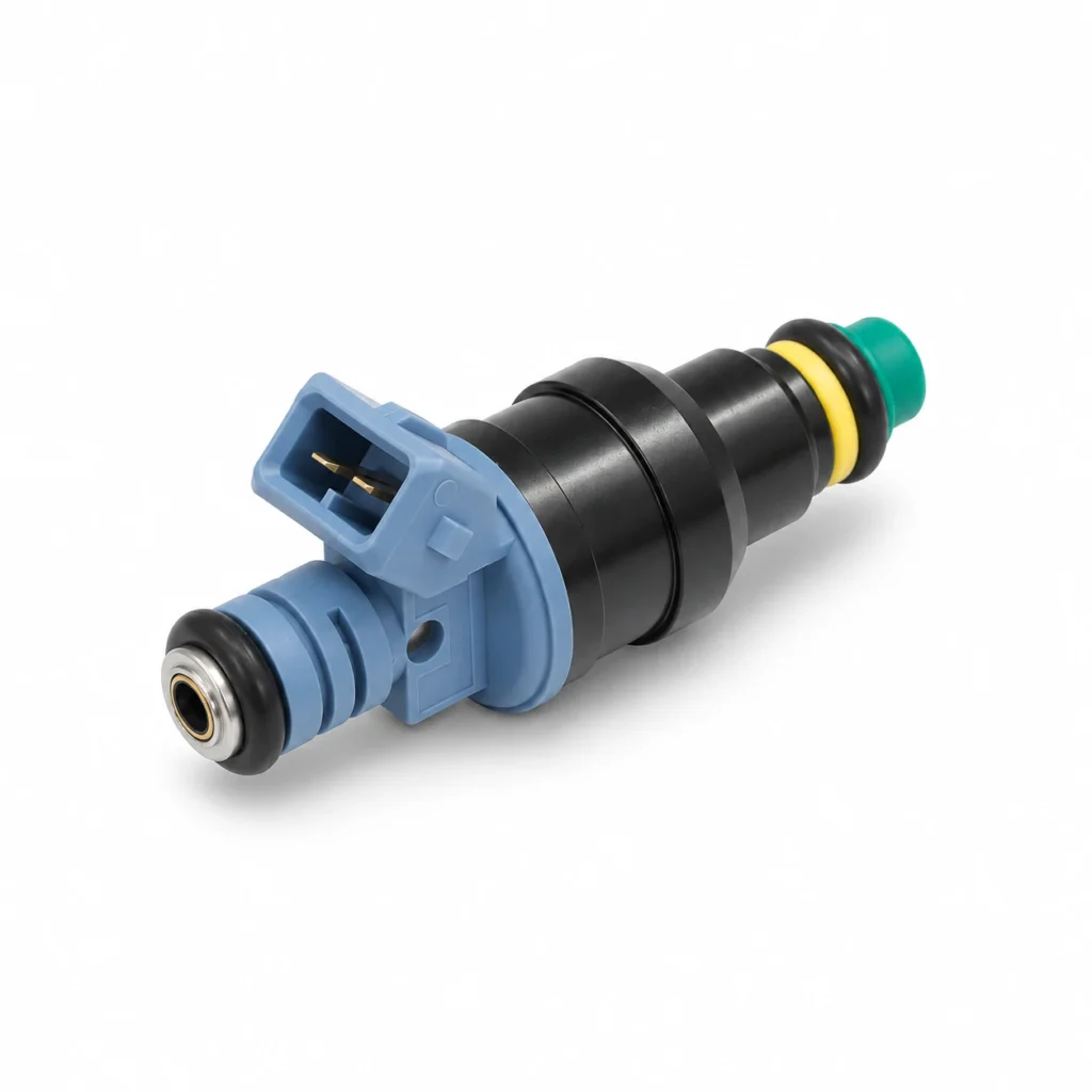
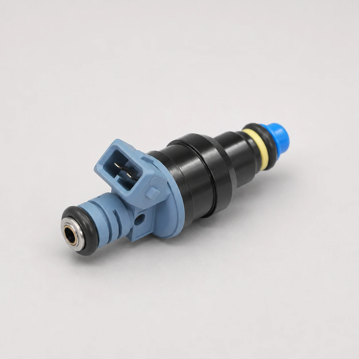
Fuel injector connector corrosion can interrupt electrical contact and contribute to a running concern, but a misfire or injector code does not prove that corrosion is the cause. Inspect the connector, seals, terminals and surrounding harness using the vehicle manufacturer’s procedure, then separate a connection fault from an injector or control-circuit fault. Do not replace a complete set of injectors from a photograph of one discolored terminal. This guide explains what evidence a workshop should preserve, how to describe the findings, and what a parts buyer needs before choosing an injector, connector repair or harness replacement.
Corrosion, fretting and damage are different observations
A useful inspection report describes what is visible before deciding why it happened. Green deposits, dark residue, liquid contamination, damaged plating, a broken latch and a terminal that has moved out of position are different findings. Record which connector half is affected and which cavity is involved. “Bad plug” is too broad to guide a reliable parts decision.
Fretting involves deterioration at a contact interface associated with small relative movement. An injector-specific example appears in GM bulletin 23-NA-027, hosted by NHTSA. For its listed diesel applications, the document discusses connector contact wear and a defined inspection and repair process. Its vehicle coverage matters: it does not establish that the port injector illustrated in this article has the same defect or requires the same repair.
A separate GM communication about contaminated ECM connectors illustrates why visible contamination and terminal corrosion require attention to the actual affected circuits. That document concerns specific ECM connectors, not a universal injector cleaning method. Use it as a reminder to identify the location and repair instructions precisely, rather than transferring one bulletin’s treatment to another connector.
Record the fault before unplugging components
Save the diagnostic codes, their status and available operating-condition data. Ask whether the concern appears after rain, during warm operation, over rough roads or following previous service. These details can help the technician reproduce the complaint, but they are clues rather than proof. An intermittent misfire can have causes outside the injector circuit, so retain the complete diagnostic context.
Photograph the connector as installed, including the latch, harness support and routing. Then follow the service instructions for safe isolation and disconnection. Do not pull on the wires or force a brittle locking feature. If access requires removing fuel-system components, that work needs its own specified pressure-relief and handling procedure. An electrical inspection should not become an uncontrolled fuel-leak risk.
When the connector is accessible, identify the viewing direction in the photographs and include a clear part reference. A close-up without orientation can make cavity identification ambiguous. Record whether moisture or residue was observed before cleaning or manipulation. Once a connector has been cleaned, repeatedly mated or repaired, the original condition may no longer be available for assessment.
Inspect the complete connection, not only the obvious stain
The technician should examine both mating sides using the correct procedure and suitable lighting. Record damaged housings, absent or displaced seals, terminal position, locking condition and wire damage near the connector. The exterior may look acceptable while the actual contact interface needs a more specific assessment. Conversely, dirt on the outside of a housing does not prove that the electrical contacts are corroded.
Terminal contact checks require the correct test tools. Pushing an oversized meter probe into a connector can change the terminal condition and create another fault. Follow the specified probing method and acceptance criteria; do not turn a subjective impression of “tight enough” into a documented pass. If the required tool is unavailable, record that the contact check remains incomplete.
Also inspect the harness route and supports identified in the vehicle information. A repaired connector should not be left carrying a load from a stretched wire or rubbing against a nearby component. These observations are particularly useful for repeated complaints, where replacement of an injector alone may leave the original connection problem untouched. The repair scope should address the confirmed condition and its documented cause.
Distinguish the connection from the injector
A workshop needs to establish what each test measures. A reading obtained through a harness includes a different path from a reading taken directly at a disconnected component. A visual inspection addresses visible condition; it does not establish injector flow, spray behavior or every aspect of electrical operation. Keep the results in separate fields instead of allowing one pass to stand for the entire system.
A Kohler service manual provides a manufacturer example of distinguishing an injector concern from wiring and electrical connections. Its equipment, test conditions and values belong to the engines covered by that manual. This article does not transfer those resistance values or test-light instructions to automotive injectors. The general diagnostic boundary is what matters: establish whether the fault is in the component or in the path that controls it.
For related background, high-impedance injector compatibility explains why electrical characteristics and the ECU driver must match. Injector flow matching addresses a separate delivery question. Neither resistance class nor flow data proves that an installed connector makes reliable contact.
Use a finding-to-action table
| Recorded finding | Evidence still needed | Repair-planning implication |
|---|---|---|
| Green deposits on a terminal | Exact affected cavity, mating-side condition and applicable repair instruction | Assess terminal and connector repair scope before ordering an injector |
| Dark contact residue | Appropriate contact inspection and vehicle-specific diagnostic result | Do not assume ordinary dirt or prescribe universal cleaning |
| Broken latch or displaced terminal | Housing identification, terminal retention and approved service parts | Check whether the connection can be restored with a permitted repair |
| Liquid inside a connector | Fluid identity where established and source investigation | Address the documented intrusion path as well as affected parts |
| Intermittent code without visible damage | Prescribed circuit and connection checks under relevant conditions | Keep injector failure unconfirmed until the diagnostic evidence supports it |
| Damaged injector-side terminal | Exact injector identity and manufacturer repair limitations | Establish whether injector replacement is required |
| Repeated complaint after repair | Previous work record, routing photographs and repeated test results | Reassess the remaining circuit rather than repeating the same assumption |
This table organizes qualitative decisions. The primary documents above illustrate application-specific contact and circuit investigations; they do not supply one universal corrosion threshold, cleaner, lubricant or replacement rule. Use the current service information for the actual vehicle.
Why cleaning is not an automatic repair
Removing a visible deposit does not establish that a contact surface, terminal spring or housing is serviceable. The correct action may involve replacement rather than cleaning, depending on the connector and manufacturer instructions. The ECM bulletin cited above specifically rejects cleaning certain corroded terminals in its covered situation. That limitation should not be reversed into a universal rule for every connector, but it clearly shows why a generic “spray and reconnect” recommendation is inadequate.
Do not scrape terminals, introduce an unspecified chemical or pack a connector with grease based on an unrelated online example. Where a manufacturer specifies a product, amount and placement, follow those instructions for that connector. Where no such instruction has been established, keep the proposed treatment unapproved. A lubricant does not restore a broken lock, displaced terminal or damaged contact geometry.
For workshop-to-supplier communication, separate an inspection from a repair. “Connector cleaned and concern currently absent” describes an observation with limits. “Connector repaired to the specified procedure and verification completed” is a stronger statement that requires supporting records. This distinction becomes important if the condition later returns or a warranty claim is submitted.
Choose the correct part and document its limits
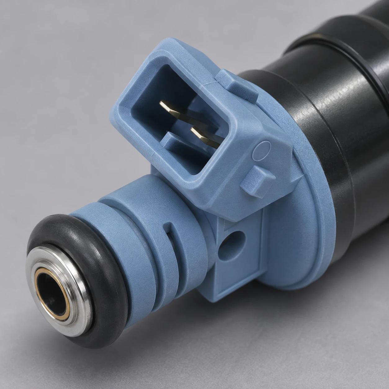
The 35310-22010 reference injector listing shows a specific blue-gray and black port-injector configuration. Its visible connector helps identify a product for an enquiry. It does not establish that any visually similar pigtail, seal, driver or injector is interchangeable. Confirm the vehicle, engine, original reference and approved replacement information separately.
When requesting a connector repair, provide the housing and terminal identification if available, cavity count, keying, seal arrangement and photographs of both mating sides. State whether an injector-side terminal is also damaged. Ask which repair parts and installation method are permitted for the application. A supplier can then distinguish an injector enquiry from a connector or harness requirement without promising a repair that the available evidence cannot support.
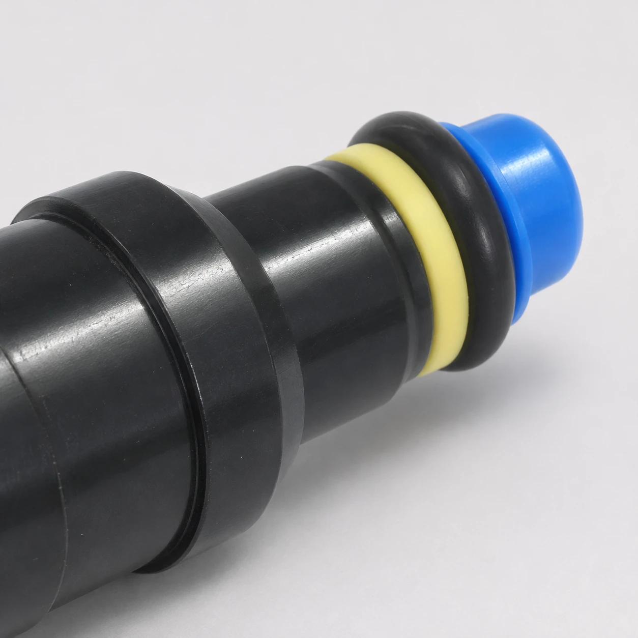
If injector removal is necessary, the fuel sealing work becomes a separate acceptance item. The injector O-ring replacement guide discusses external port-injector seal planning and leak checks. A successful electrical repair does not waive those fuel-system requirements, and a leak-free seal does not establish reliable electrical contact.
Verify the repair against the original complaint
The final record should list the confirmed finding, replaced or repaired parts, relevant routing changes and verification conditions. Repeat the checks required by the service procedure and state whether the original concern returned. Avoid claiming that a brief idle period reproduces every intermittent operating condition. If the concern could not be reproduced before repair, preserve that limitation in the final report.
For fleet or distribution work, retain the connector photographs and job reference with the returned component. A clear evidence package helps distinguish repeated installation damage, an unresolved harness concern and an actual component fault. It also makes future stock decisions more accurate because a connector repair is not incorrectly counted as an injector failure.
Educational video: understand injector electrical operation
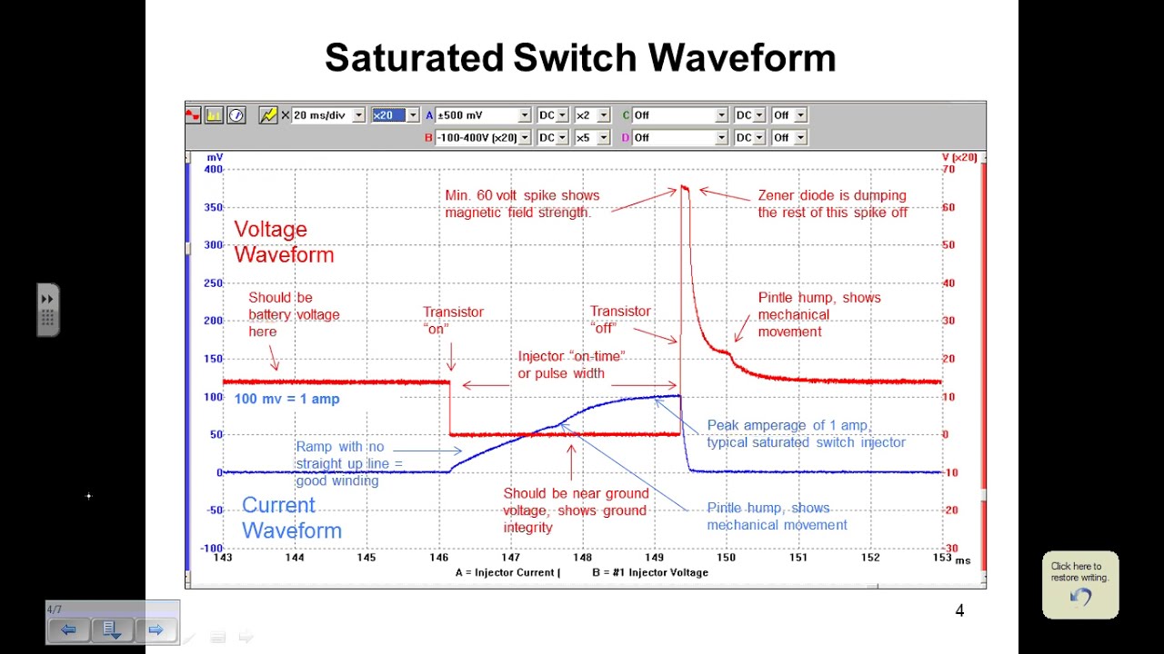
ScannerDanner: How to interpret fuel injector waveforms (a ScannerDanner Premium video)
This diagnostic lesson explains injector waveform interpretation. It supports the distinction between an electrical command and the injector’s response. It does not provide a universal corrosion test, terminal specification or instruction to energize an injector directly.
FAQ
Can a corroded injector connector cause a misfire?
A poor electrical connection can contribute to an injector operating concern, but a misfire alone does not establish that cause. Confirm the affected circuit and follow the vehicle’s diagnostic procedure.
Should every corroded connector simply be cleaned?
No universal cleaning rule applies. Determine the terminal and housing condition and follow the specified repair method. Some manufacturer instructions require replacement of affected terminals rather than cleaning.
Does an injector resistance reading prove the connector is good?
No. Interpret the reading according to where and how it was taken. A component measurement and a connection assessment address different parts of the system and may require separate checks.
What should accompany an injector connector parts request?
Include vehicle identification, original part reference, connector orientation, cavity details, photographs of both sides and the technician’s confirmed finding. State whether the injector terminal, harness terminal or housing is affected.