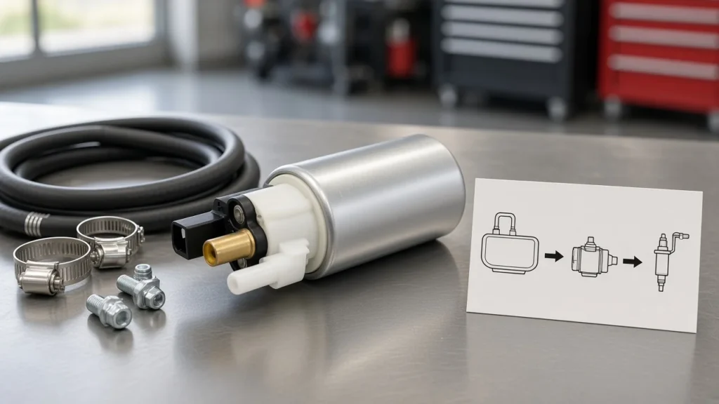
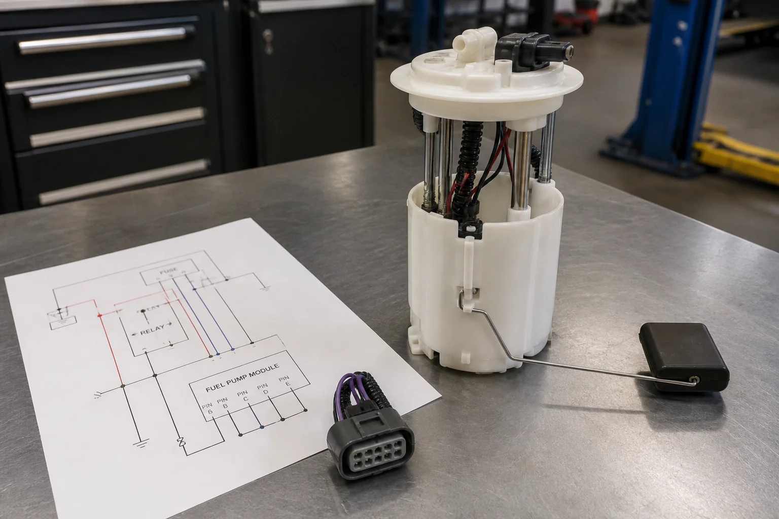
An in tank fuel pump wiring diagram is a pin-role map for the tank module connector: separate high-current pump power and ground from the fuel-level sender circuits, then trace how fused battery power reaches that connector through a relay and any inertia or oil-pressure safety device in the path. Use this page to read the diagram—not to drop the tank or build a full 12-volt pump harness from scratch. Below: power-path topology, 3-wire vs 4-wire pin roles, why wire colors mislead, sender ohms, safety boxes on the schematic, sister-page handoffs, and when to browse a Kangsong in-tank module.
What an In-Tank Fuel Pump Wiring Diagram Shows
A module wiring diagram maps which cavities on the in-tank module harness are pump motor circuits versus fuel-level sender circuits, and how those pins sit relative to upstream fuse and relay symbols.
An in-tank fuel pump module is the tank-mounted unit that usually combines the electric pump with a float-driven sender and presents one external connector (or a small connector family) to the vehicle harness. The diagram’s job is literacy: which line is thick pump power, which is ground, which thin wire is sender signal, and—on many newer maps—which pin is a dedicated sender low-reference back to the PCM.
Fuel pump module wiring literacy is a different reader job from “how do I install the assembly” or “how do I wire a generic 12-volt pump with a new relay kit.” Those sisters matter later; first you have to read the map without mixing pin jobs.
Shop counters see the same failure pattern repeatedly: a tech assumes every colored wire on the tank plug is pump power, jumpers the wrong cavity, and either cooks a sender circuit or leaves the pump dark while the gauge still moves. Diagram literacy stops that before parts get ordered.
Trace the Power Path: Fuse, Relay, and Module Feed
Fused battery power is relay-switched before it reaches the tank module; the ignition or PCM trigger only energizes the relay coil, not the full pump amperage.
Start at the left of a typical OEM-style gasoline map and walk right: a battery-hot fuse (one Ford EVTM-style example labels a 20 A FUEL PMP fuse) feeds the fuel pump relay contacts. Relay output then travels toward the tank—often through an inertia fuel shutoff—before it arrives at the module’s pump power pin. The relay note on that style of page is blunt: the relay directs voltage to the fuel pump and the PCM side of the control story.
Independent safe-wiring education makes the same architectural point for electric pumps in general: keep the high-current RED feed on a fused battery path switched by a relay, size the pump power circuit conductors for voltage drop (about 12 gauge for big pumps and 14 gauge for smaller ones in that guide), and keep the pump ground the same gauge as the positive lead. Control-side switches belong on the coil/trigger path.
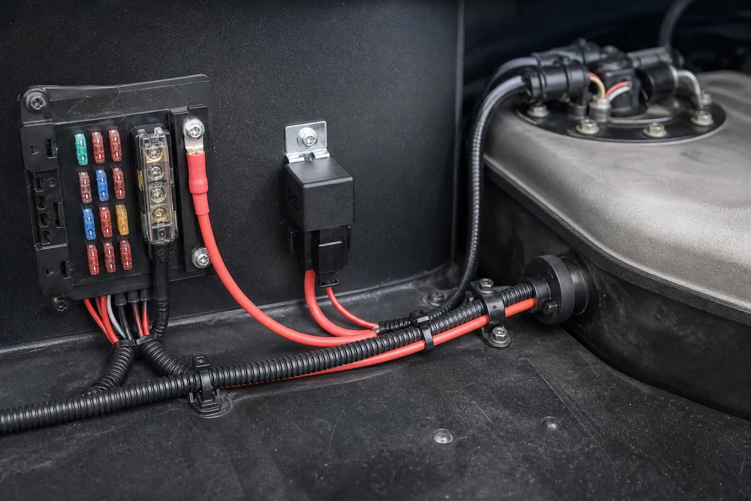
If you are choosing the cube amp class or building a new harness from blank wire, stop here and open the sister pages on relay sizing and (when published) 12-volt pump wiring. This article only needs you to recognize those symbols on the in-tank map so you do not treat a thin trigger wire as the pump feed.
Module Pin Roles: Power, Ground, Sender, and Low-Reference
Separate high-current pump pins from sender signal pins; on many 4-wire modules a fourth thin wire is sender low-reference to the PCM, not a second pump power.
Use roles first, colors second. Community harness notes on older GM-style 3-wire tanks often resolve to a simple trio: chassis ground, pump power, and a single sender signal to the gauge. Newer truck harnesses add a dedicated low-reference so the PCM sees a cleaner fuel-level reading for EVAP logic—grounding that low-ref to chassis “because it looks like a ground” can upset the module’s intended return path.
| Pin role | What it does | Typical cues on a diagram | Common mistake |
|---|---|---|---|
| Pump power | High-current feed to the pump motor | Thick wire from relay / inertia path into the module | Feeding it from a thin ignition wire without a relay |
| Pump / module ground | Return for the pump motor (often chassis at the tank) | Ground symbol or heavy black ground run | Sharing a corroded sheet-metal screw with unrelated loads |
| Sender signal | Variable-resistor output for fuel level | Thin wire to cluster or PCM fuel-level input | Jumping it to 12 V “to test the gauge” |
| Sender low-reference (4-wire) | Dedicated return for the sender circuit | Thin wire labeled low ref / signal ground to PCM | Tying it to chassis and calling the fourth pin “extra power” |
| Module pattern | Usual circuit count | What you should see | What changes in service |
|---|---|---|---|
| 2-wire pump-only lead | Pump + and ground | No sender on that plug | Sender may live on a separate connector |
| 3-wire in-tank harness | Power, ground, sender signal | One thin sender wire with shared ground strategy | Color codes vary by OEM and age |
| 4-wire in-tank harness | Power, ground, sender signal, low-ref | Second thin wire for PCM-side return | Do not treat low-ref as pump power |
Tip: On a 4 wire in tank fuel pump wiring diagram, the extra thin wire is often sender low-reference—not a second high-current pump feed. Confirm the cavity callout before you splice (source: module pin-role reading against OEM-style maps such as SuperMotors fuel pump / sender diagram).
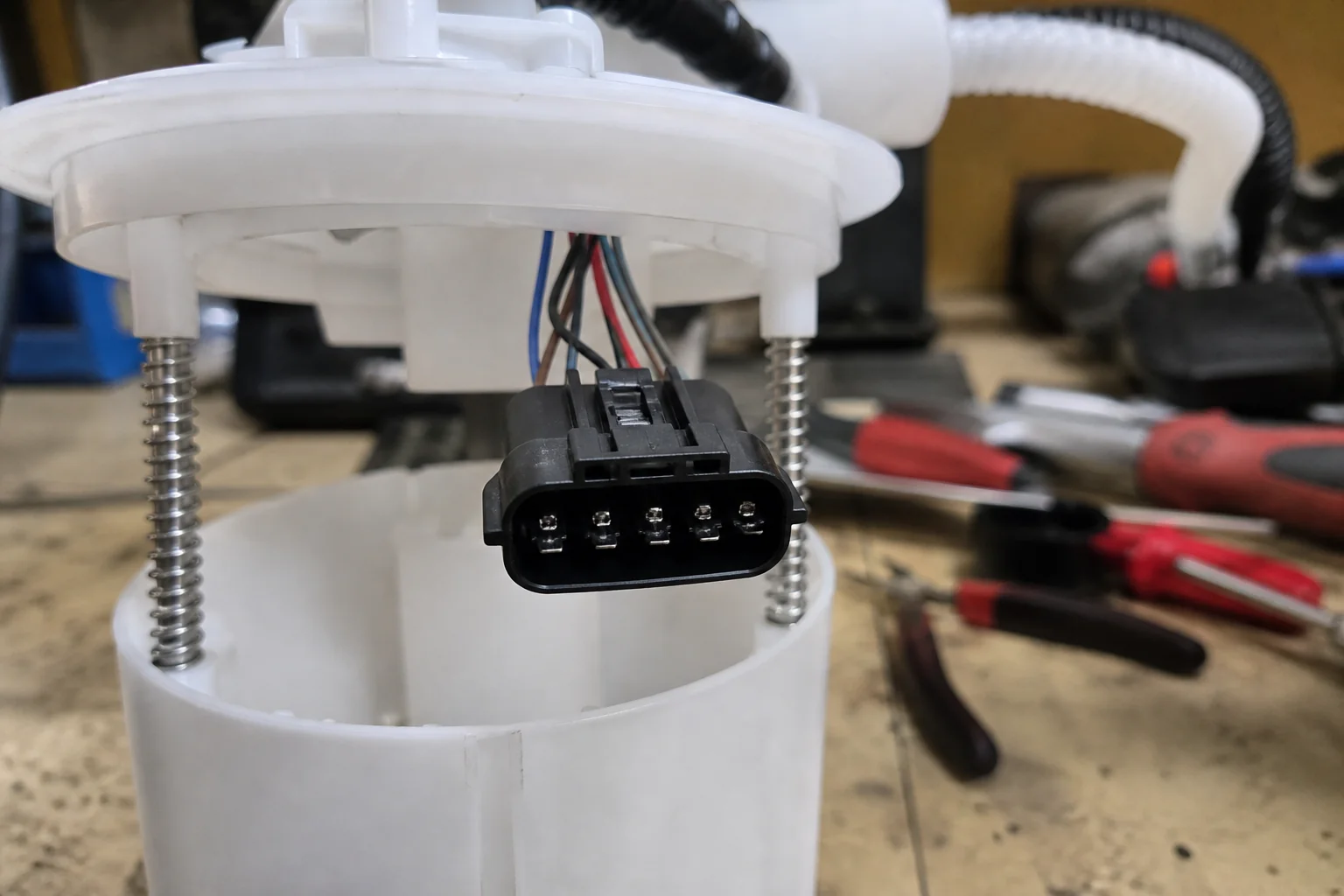
Aftermarket in-tank modules sometimes use multi-pin power/ground pairs plus separate sender resistance leads. The portable rule stays the same: read the sheet that came with the module you are installing, then map roles—never invent a universal color chart.
Wire Colors vs Pin Roles (Why Colors Alone Mislead)
Match cavity roles on the OEM or module sheet; faded insulation and replacement pigtails make color memory unreliable.
Field threads on third-gen F-body tanks show why: tan pump-power wire fades toward white or gray outdoors, while purple sender leads can look pink depending on whether you are reading the tank harness or the body connector. Replacement Delphi-style pigtails introduce yet another palette that does not match the OE loom—orange/brown pairs on some platforms are sender-related, not automatic proof of pump power.
So when someone asks “what color wires go to the fuel pump?” the honest counter answer is: whatever color the diagram assigns to the pump power cavity on that VIN and module revision. Teach roles at the counter; then verify colors on the print for that vehicle.
Important: If insulation looks sun-bleached or a replacement connector arrived with new colors, stop guessing. Probe or continuity-check by cavity role against the diagram before applying battery voltage (source: role-first reading on SuperMotors fuel pump / sender diagram; community wire-fade notes kept in Research only).
Reading the Fuel Level Sender on the Same Diagram
The sender is a float-driven variable resistor sharing the module connector family; empty-to-full ohm values are platform-specific examples, not a universal chart.
On one Ford EVTM-style gasoline page, the fuel gauge sender is described as a variable resistor on a float with example resistances around 16 ohms empty and 160 ohms full, feeding the instrument cluster on its own circuit while the pump uses the high-current path through the inertia switch. Other pages in the same archive family list different empty/full pairs. Treat those numbers as diagram-scoped examples only.
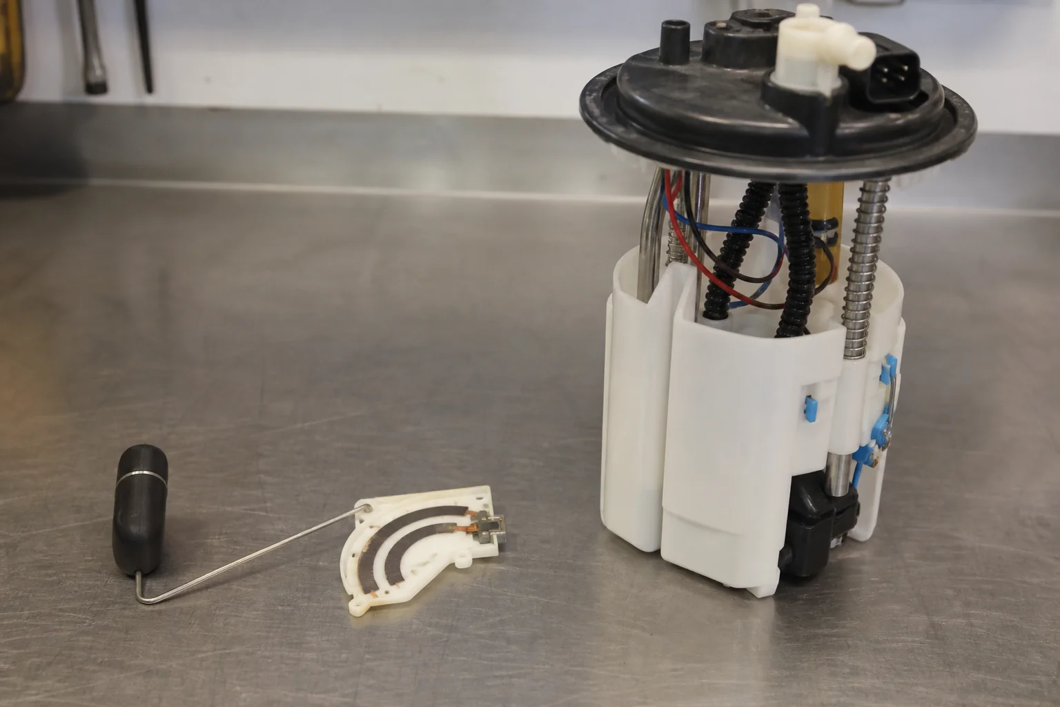
That split is why a truck can crank with no fuel pressure while the gauge still sweeps, or show a dead gauge with a loud healthy pump: the diagram put two jobs on one connector family. When the physical plug itself is the problem—broken CPA, bent pins, no click—hand off to the sister guide on disconnecting the fuel pump electrical connector rather than rewriting the pin map here.
Inertia and Oil-Pressure Devices on the Diagram
Crash and oil-pressure devices sit in the feed or control path so the pump does not stay live after impact or without oil pressure.
OEM maps that include an inertia fuel shutoff place it in series with pump power after the relay. Independent diagnostic write-ups describe the device as a mechanical cutout: a magnet-held ball leaves its seat on a sharp jolt, opens the contacts, and stays open until someone presses the reset. Symptom language is simple—crank, no start—until the button clicks home.
Safe aftermarket-oriented diagrams often add a normally-open oil pressure switch on the control side so the relay drops out if oil pressure never builds, and keep the Inertia / IFS switch normally closed until impact. Neither device replaces a correctly fused relay feed; they are boxes on the map you must account for when the module has battery at the fuse but silence at the tank.
If the schematic shows IFS and the pump never primes after a curb strike or shop-bay jolt, reset/test that switch before condemning the in-tank module.
In-Tank Diagram vs Inline and 12-Volt Wiring Sisters
Inline and dual-pump diagrams are not the same job as reading an in-tank module pin map; full 12-volt install and assembly R&R belong on sister pages.
People Also Ask mixes “how to wire in a tank fuel pump,” “how to wire an in line fuel pump,” and 3-wire questions on the same SERP. Keep the fence clean:
- This page: in-tank module diagram literacy—pin roles, sender, fuse/relay/inertia symbols.
- Connector unplug/reconnect mechanics: how to disconnect a fuel pump electrical connector.
- Tank-drop / assembly install sequence: how to install a fuel pump assembly.
- Relay contact amp class: what size relay for a fuel pump.
- Generic 12-volt pump harness build: how to wire a 12 volt fuel pump.
Do not collapse those intents into one mega-guide. The reader who opened an in tank fuel pump wiring diagram query usually needs the pin map first.
Choose a Kangsong In-Tank Fuel Pump Module After the Diagram
After the diagram roles are clear, browse a scoped Kangsong in-tank fuel pump module assembly and confirm vehicle/OE fitment before ordering.
When the harness map says the module itself is weak—no pressure with verified power and ground at the pump cavities—move to parts, not more wire theory. Kangsong publishes in-tank module assemblies for distributor channels, including module-with-float examples such as the Kangsong in-tank fuel pump module assembly (example with float). Confirm the vehicle and OE references on the SKU; catalog navigation stays on the products root category.
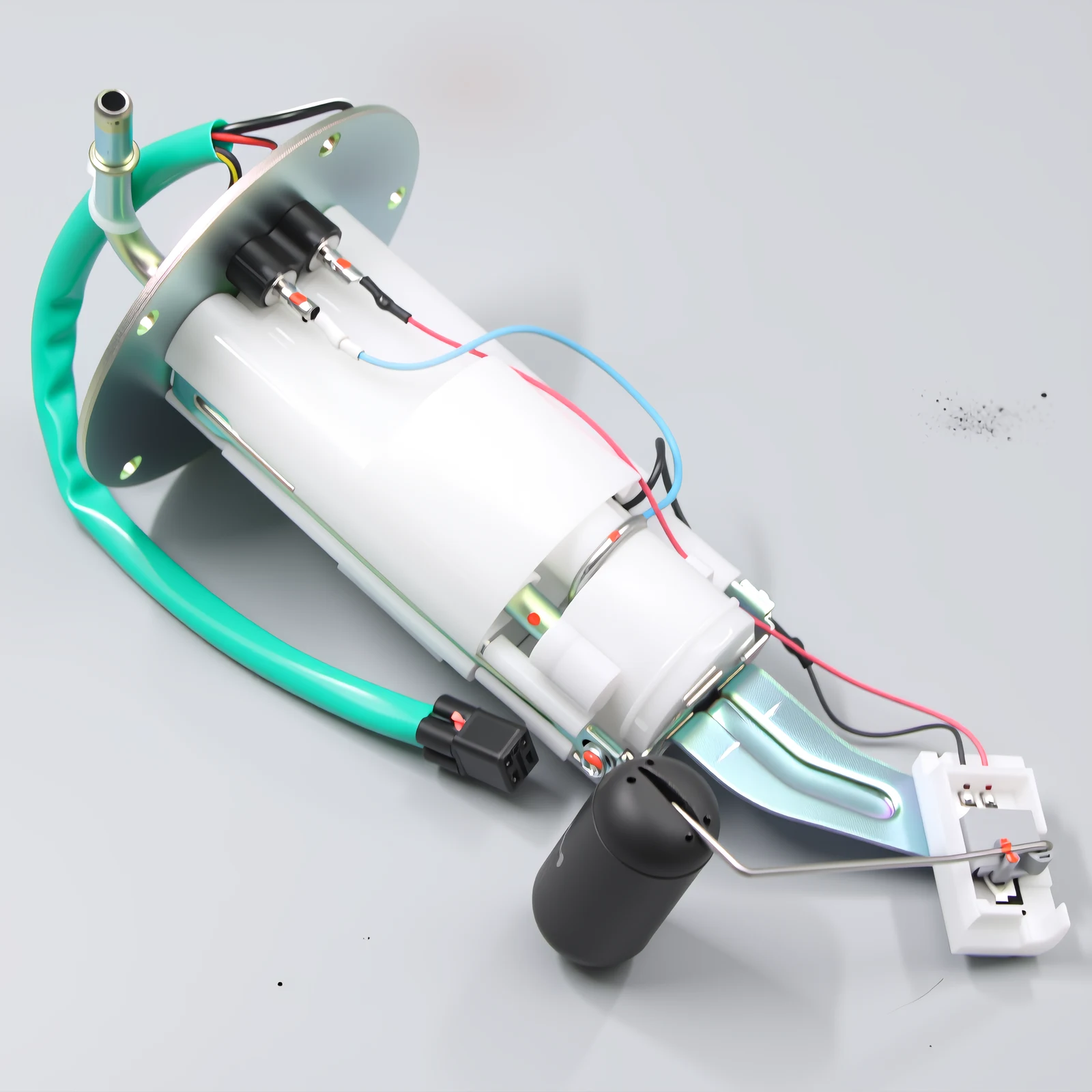
This is not a universal-fit claim and not a third-party brand substitute statement. Match the module to the diagram’s connector family and the vehicle’s OE callouts, then decide whether the next buy is the module, a connector repair, or a correctly sized relay on the feed path.
FAQ
How do I read an in-tank fuel pump wiring diagram?
Start by separating pump power and ground from sender circuits on the module connector, then walk upstream from those pins through any inertia switch to the relay and fuse. Roles first; colors second.
What color wires go to the fuel pump?
Whatever color that vehicle’s diagram assigns to the pump-power cavity. OEM palettes differ, and outdoor fading changes tan/gray looks—verify the print for that VIN and module.
How is a 3-wire in-tank fuel pump wired?
A common pattern is pump power, chassis ground, and one sender signal. Confirm which of the three cavities is which on the OEM sheet before splicing a replacement pigtail.
What does a 4 wire in tank fuel pump wiring diagram add?
Often a dedicated sender low-reference back to the PCM so fuel level is measured on a controlled return. It is usually not a second high-current pump feed.
Are orange and brown wires the pump power?
Not automatically. On some platforms those colors sit on sender-related circuits while pump power uses a different pair—match cavity roles, especially after a color-mismatched replacement connector.
Is an inline fuel pump diagram the same as an in-tank module map?
No. Inline and dual-pump drawings solve external plumbing and feed architecture; an in-tank module map also has to account for sender pins on the same connector family.
Why is there an inertia switch on the wiring diagram?
It is a crash (or sharp-impact) cutout in series with pump power on many OEM maps. When tripped it stays open until reset, which presents as crank / no-start with a silent pump.
Do I still need a relay if the module has a factory plug?
The factory plug does not erase the high-current rule. Pump amperage still belongs on a fused battery feed switched by a relay; the plug only defines how that feed and the sender circuits enter the module.
References
- GTSparkplugs — Electric Fuel Pump Wiring Diagram — fused relay feed, wire-gauge guidance, oil-pressure and inertia control-path devices.
- SuperMotors — Ford fuel pump / inertia / sender wiring diagram (EVTM-style) — fuse → relay → inertia → tank pump/sender topology and example sender resistance callouts.
- TroubleshootMyVehicle — Fuel pump inertia switch function and reset — mechanical crash cutout behavior and crank/no-start symptom language.
- Stinger Performance forum — 255 LPH or larger fuel pump wiring diagram — community high-flow pump wiring discussion reinforcing fused relay feed and voltage-drop concerns.