If fuel pump pressure drops after shutdown, compare the pressure loss with the vehicle manufacturer’s residual-pressure specification before blaming the pump. A falling reading can involve a leaking test connection, an external fuel leak, an injector, a regulator or bypass path, or backflow through the pump-side retention system. The gauge shows that pressure changed; it does not identify which path released it. Some pressure change may be permitted, and temperature can affect the reading after a hot engine stops.
This guide focuses on interpreting gasoline supply-system leakdown evidence. It does not provide a universal pressure limit or a procedure for opening a direct-injection high-pressure circuit.
What should happen to fuel pressure after shutdown?
When the pump stops, the fuel system may retain pressure through its check valve and other sealing components. In the application described by Toyota’s Engine Control Systems I training material, retained pressure supports restarting and helps resist fuel vapor formation during hot soak. That explains the purpose of retention, not a universal pass value for every vehicle.
The expected behavior depends on the exact fuel system and test point. A low-pressure supply measurement on a gasoline direct-injection engine is different from a high-pressure rail reading. Pressure in one circuit should not be interpreted using the other circuit’s limits. Identify the engine and the measured circuit first.
Nor should every post-shutdown change be called a leak immediately. Fuel and surrounding components can change temperature after shutdown. The reading may initially rise, stabilize, or fall according to the system and conditions. Use the specified starting condition, waiting interval, and minimum retained pressure rather than demanding that every gauge remain motionless overnight.
For the underlying delivery architecture, see our return versus returnless fuel-system comparison. A regulator near the tank creates a different diagnostic arrangement from an engine-side regulator with a liquid return line.
Record the pressure loss before interpreting it
A useful leakdown record begins with the procedure reference. Write down the vehicle identification, engine code, test location, gauge range, units, fuel-system type, and temperature condition. Include whether the system was running, commanded with a diagnostic tool, or pressurized by the specific prime method called for in the procedure.
Record the pressure at the defined starting point and at each required interval. Note exactly when the engine or pump stopped. A photograph of a gauge taken several minutes later cannot reconstruct the initial value or the elapsed time. When possible, save a continuous record with a clear time reference.
Check the test setup before drawing conclusions. An imperfect adapter seal, loose fitting, leaking relief valve, or unsuitable connection can create pressure loss that was not present before the equipment was fitted. Ensure the instrument and adapters are rated for the fuel and circuit, and follow their instructions. Never infer that a tool suitable for a supply line is also suitable for direct-injection rail pressure.
The Mityvac MV5545 manufacturer’s manual includes a pressure-leakdown test and distinguishes fuel-system configurations. Its procedures apply to that equipment and its stated applications; they should be used alongside current vehicle service information, not copied as a universal test.
Which paths can let residual pressure escape?
| Possible path | Why it matters | Evidence needed | What the gauge alone cannot prove |
|---|---|---|---|
| Tester or adapter leak | The measurement setup can introduce its own pressure loss | Correct installation, approved sealing checks, and a verified instrument | That the original vehicle circuit has failed |
| External fuel leak | Fuel may escape through a connection, pipe, seal, or component | Approved inspection of the actual circuit, with ignition sources controlled | The leak location or whether operation is safe |
| Injector leakage | A leaking injector can release fuel beyond its intended closed state | The manufacturer’s injector leakage or related diagnostic checks | Which injector is affected |
| Regulator or bypass path | A control component may allow pressure to bleed away in the relevant layout | Correct identification of the regulator and an approved isolation or functional test | That the regulator is defective in every system |
| Pump-side retention path | Fuel may flow back toward the tank through an ineffective retention component | Application-specific testing that separates this path from the other possibilities | That the pump motor or complete assembly must be replaced |
This is a diagnostic comparison, not a parts-replacement chart. Several paths may coexist. The manufacturer’s sequence should determine which checks are required and how any section may safely be isolated.
A pump check valve is one candidate, not the automatic answer
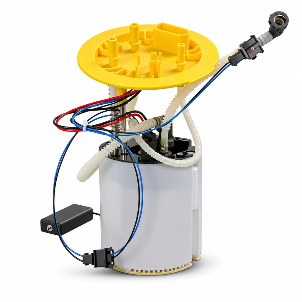
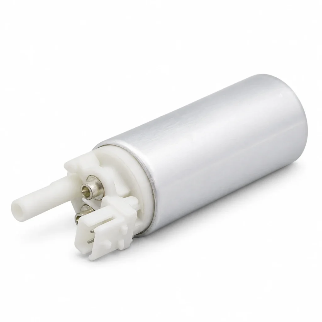
A check valve can help retain pressure after pump shutdown, but a pressure decline does not single it out. Its location and serviceability vary. A valve may be part of a pump element, a module, or a separate documented component. Establish the actual design before deciding what the repair should include.
Our fuel pump check-valve guide explains component identification. For a shutdown pressure loss, compare all plausible paths before selecting a replacement.
Injector or regulator evidence may point away from the tank
Long cranking, an unusual restart, or a rich-running complaint can guide the next diagnostic step, but these symptoms are not exclusive to injector leakage. Likewise, the presence of a regulator in the fuel system does not prove it caused the pressure loss. Symptoms, component layout, and the approved tests need to be considered together.
A regulator may be integrated into a tank module or located elsewhere. Do not identify a rail-mounted object as a regulator merely because it resembles one; it may perform a different function. The pressure-regulator identification guide covers that distinction.
A practical investigation sequence for workshops
First, address any visible fuel escape, strong fuel odor, damaged line, or wet fitting using the vehicle’s safety procedure. Do not keep starting the engine to collect more data when the system may be leaking externally. A pressure-retention complaint never justifies ignoring a potential fire hazard.
Second, confirm that the original complaint and the test result are repeatable under the specified conditions. A cold test and a hot-soak restart test may tell different stories. Record the difference instead of combining them into one unsupported conclusion.
Third, verify the measurement equipment and identify the relevant pressure-control arrangement. Compare the recorded values with the actual service limits. If a reading passes the specified retention test, investigate the remaining causes of the starting complaint rather than extending the waiting time until some pressure decline appears.
Fourth, follow the prescribed method for distinguishing the possible leak paths. Do not crush a nylon line, clamp an unknown hose, cap an unidentified return connection, or block a pump outlet as an improvised isolation test. Appropriate adapters, shutoff arrangements, and test sequences depend on both the system and the approved equipment.
Finally, keep the findings separate from the proposed repair. “Residual pressure below the specified minimum, tester verified, pump-side path isolated by the approved procedure” supports a different decision from “gauge dropped after I turned the key off.” Preserve that distinction in the job record and supplier inquiry.
Does easier starting after another prime prove a bad pump?
No. If an additional approved prime improves starting, it suggests that the changed conditions helped the engine start. It does not identify where pressure was lost, prove inadequate running delivery, or rule out another starting fault. Do not turn repeated key cycling into a substitute for the proper diagnostic sequence.
Pressure retention and operating delivery are also different questions. A pump may deliver the specified fuel while running but fail a retention-related check. Conversely, a system may retain pressure yet fail to provide enough fuel under demand. Test the function associated with the complaint before choosing a repair.
Choose the replacement scope after the leak path is established
Once the failed component has been identified, confirm its original reference and service scope. A bare pump, a complete module, an injector, a regulator, and a seal are different purchases. A complete assembly should not be ordered simply because it is the largest part near the tank.
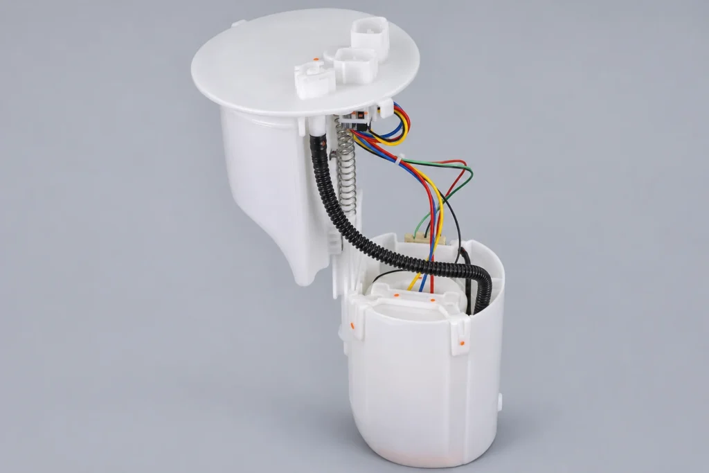
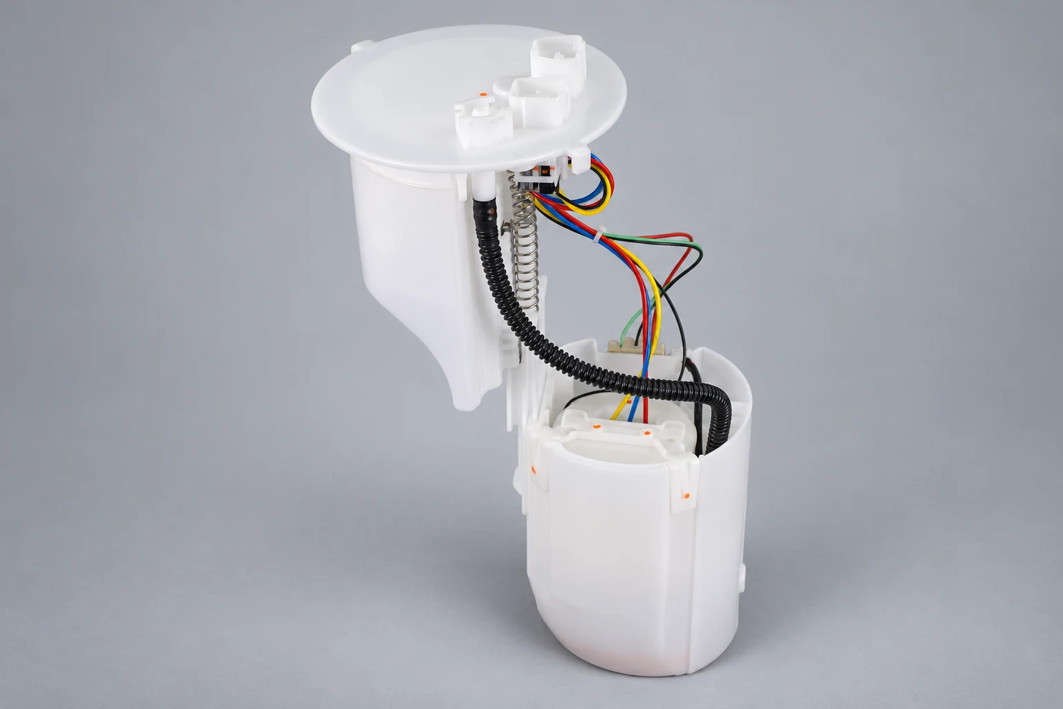
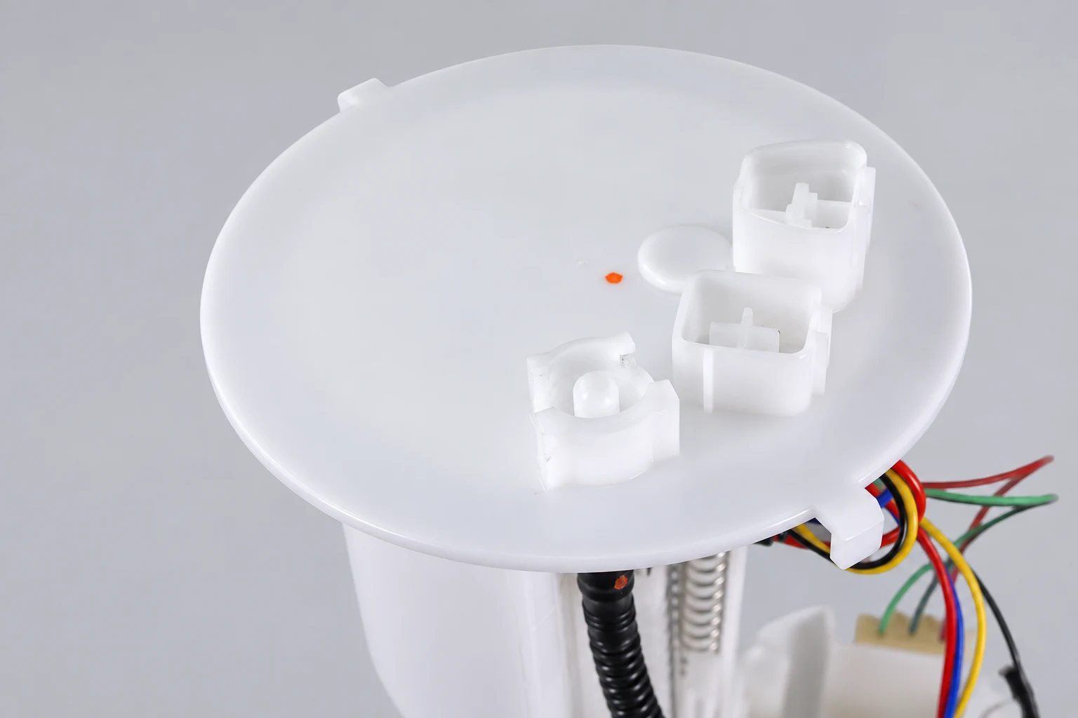
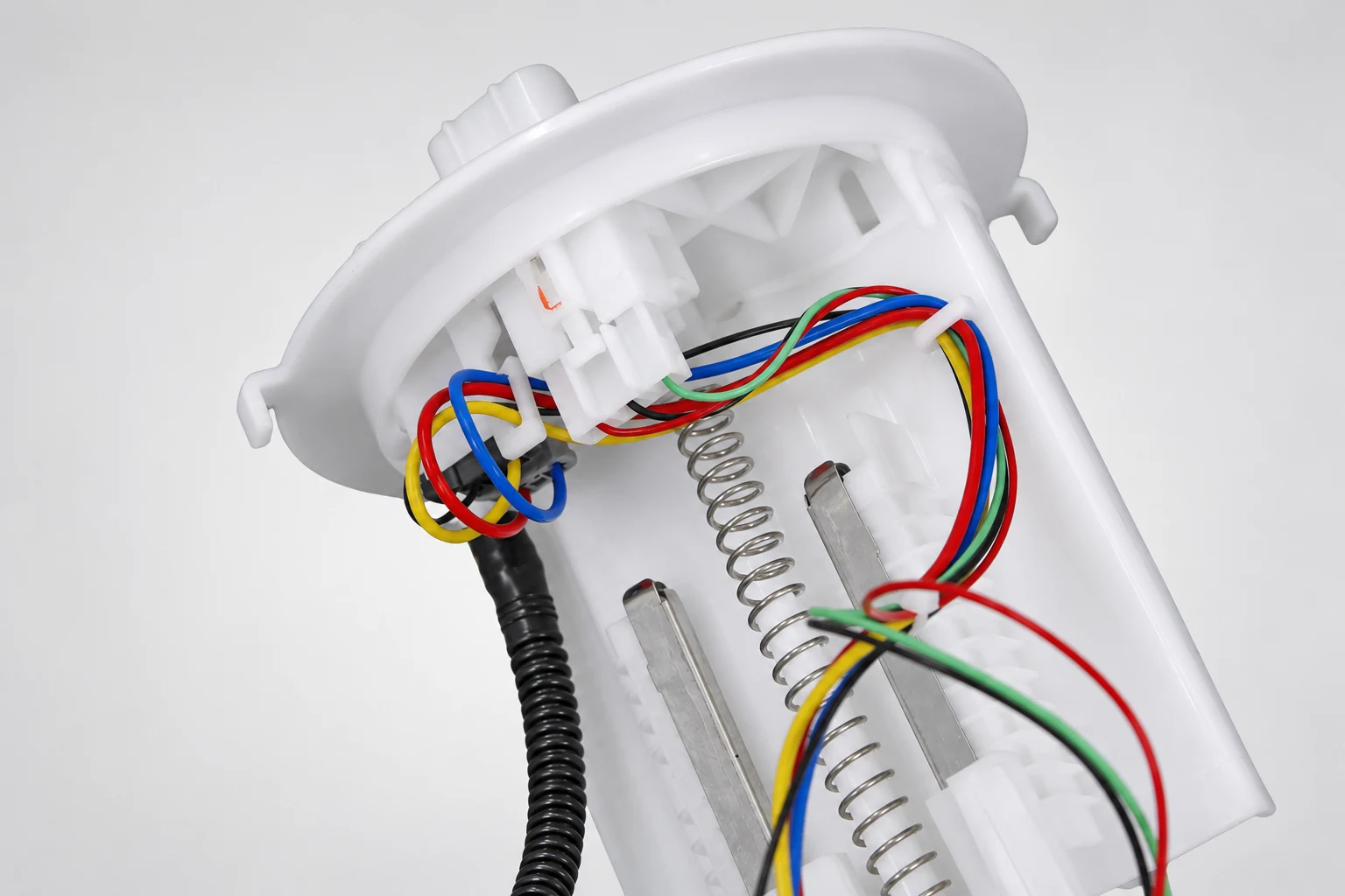
The Kangsong Toyota Camry application module listing is one application-specific catalog example. Confirm the original part reference, vehicle details, included components, and interfaces before requesting a quote. The illustration does not claim that this module has failed, nor that it is the answer to every residual-pressure complaint.
A useful inquiry includes the pressure record, procedure reference, test location, units, temperature condition, and the checks that established the leak path. Add photographs of the original label and interfaces. After repair, repeat the relevant tests and prescribed leak checks, then record the final result against the original complaint.
Fuel-system work also requires suitable ventilation, ignition-source control, and safe handling of retained fuel. The HSE motor-vehicle repair guidance covers workshop fire, explosion, and other repair hazards. Use current vehicle and equipment instructions for the actual job.
Watch: understand the regulator’s function
TechTrixInfo’s educational animation explains a pressure regulator valve. It helps distinguish the regulating function from a pump’s retention function; it does not provide a leakdown threshold or an isolation procedure for your vehicle.
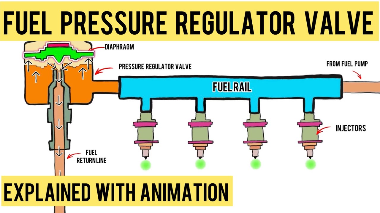
Watch the pressure-regulator animation on YouTube.
Frequently asked questions
Should fuel pressure stay exactly the same after shutdown?
Not necessarily. Use the vehicle’s required test conditions, observation interval, and retained-pressure limit. Temperature changes and system design can affect the reading.
Does a rapid pressure drop prove the pump check valve is bad?
No. The tester, external connections, injectors, regulator or bypass path, and pump-side retention components must be distinguished using the approved diagnostic method.
Can a pump run normally but fail a pressure-retention check?
Yes. Running delivery and shutdown retention are different functions. Establish the failed component and its service scope rather than assuming the motor or whole module is defective.
Can I use the same gauge for a supply line and a direct-injection rail?
Only if the equipment is explicitly rated and approved for that circuit and procedure. A supply-side gauge must not be assumed suitable for direct-injection high pressure.